-
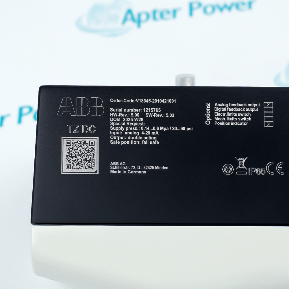
Match the complete marking
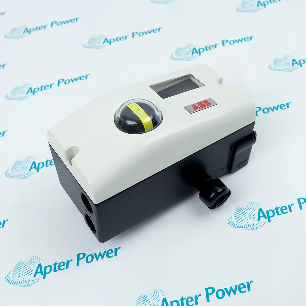
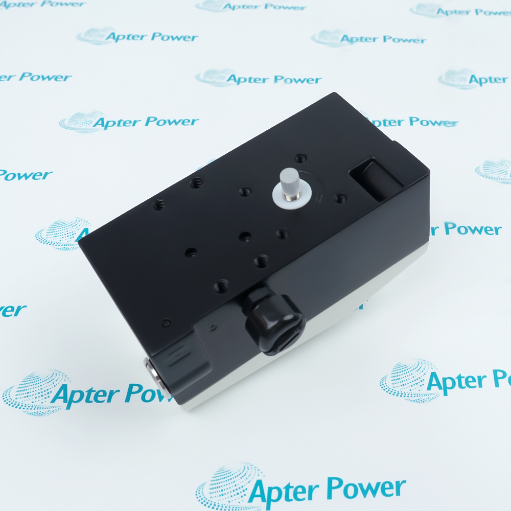
Match both pneumatic outputs, the fail-safe response, 4–20 mA input and feedback circuits, NPT connections and actuator linkage. Do not infer HART or hazardous-area approval from the TZIDC family name.
-
Check the offered item before ordering
This positioner requires a matched pneumatic actuator, suitable attachment kit and clean instrument air. External mounting accessories and air-treatment assemblies are included only when itemized.
Technical specifications for V18345-2010421001
-
Manufacturer:ABB
-
Product Category:General Automation
-
Spare Part Number:V18345-2010421001
-
Weight:1.65 kg
-
Tariff Code:8537101190
-
Setpoint input:4–20 mA, two-wire
-
Position feedback:4–20 mA, two-wire plug-in module
-
Local communication:LCI adapter connection
-
Pneumatic output:Double acting, fail safe
-
Air supply pressure:1.4 to 6 bar; respect actuator maximum
-
Pneumatic output range:0 to 6 bar
-
Air consumption:<0.03 kg/h, independent of supply pressure
-
Cable-entry thread:1/2-14 NPT
-
Air-port thread:1/4-18 NPT
-
Position indication:Mechanical indicator and LCD
-
Linear-actuator operating angle:25° to 45°
-
Minimum configured travel span:>20% of total travel
-
Travel-time prolongation:0 to 200 seconds per direction
-
Characteristic deviation:≤0.5%
-
Configurable dead zone:0.1 to 10%
-
Tolerance band:0.3 to 10%
-
Conversion resolution:>16,000 steps
-
Sampling interval:20 ms
-
Air particle size:5 µm maximum
-
Air oil concentration:1 mg/m³ maximum
-
Pressure dew point:10 K below operating temperature
-
Housing protection:IP65 / NEMA 4X; no overhead mounting for NEMA 4X
Information
- ABB V18345-2010421001 closes the valve-position loop by comparing actuator position with the electrical setpoint. Its I/P stage meters air through a pneumatic amplifier, reducing air flow once the target position is reached.
Signals: 4–20 mA setpoint and analog position feedback
Connections: 1/2-14 NPT cable entry and 1/4-18 NPT air ports
The double-acting pneumatic stage uses a 1.4 to 6 bar air supply, subject to the actuator's pressure limit. For this fail-safe version, loss of electrical power depressurizes output 1 and pressurizes output 2. The resulting valve movement depends on the actuator arrangement and which chamber is connected to each output; it is not inherently a universal valve-open or valve-closed action.
Local parameter access is available through the LCI adapter connection; this order does not include the optional FSK communication module for HART over the current loop. The positioner supports a configurable 0.1 to 10% dead zone and a 0.3 to 10% tolerance band, allowing positioning behavior to be adapted to the actuator rather than relying on one fixed response setting.
V18345-2010421001 Official TZIDC Datasheet Excerpt
Original operating principle, adjustment, mounting, performance and full order-code tables. PDF · 10 pages.V18345-2010421001 Installation & Verification Guide
Double-acting pneumatic connections, separate signal loops, Auto Adjust and controlled valve travel tests. PDF · 5 pages.
Application scope: The selected device is double acting and has no explosion-protection option. Its application must match the full order code; do not apply family-level single-acting SIL claims or optional HART features to this configuration.
Double-acting valve positioning
Control both actuator chambers while retaining the selected fail-safe pneumatic response.Linear valve actuators
Use an appropriate DIN / IEC 534 / NAMUR attachment with valid linkage travel and feedback angle.Rotary valve actuators
Fit a VDI / VDE 3845 attachment and confirm rotational direction during Auto Adjust.Analog loop integration
Integrate the setpoint and position feedback as separate 4–20 mA loops in the control system.
Isolate the process and clear the stroke area before adjustment or power-loss tests.
Use 1.4 to 6 bar supply and remain below the actuator maximum.
Identify setpoint and feedback terminals and polarity before connection.
Use the specified cable and air-port thread types.
Check output 1 depressurization and output 2 pressurization against actual valve motion.
Check endpoints, control deviation, feedback and alarm behavior before release.
Alternative Names
Technical notes
Pneumatic action: The selected fail-safe arrangement is double acting. Confirm which actuator chamber each output serves.
Signal interfaces: Keep the input and analog feedback loops separate. LCI access does not imply an installed FSK module.
Adjustment: Auto Adjust may move the actuator through its travel. Use an approved process state and inspect the resulting limits.
Technical reference: ABB TZIDC Digital Positioner, DS/TZIDC-EN Rev. I.

FAQ View All FAQ
-
Does V18345-2010421001 include HART communication over the setpoint loop?No. Input option 1 selects the two-wire 4–20 mA input and LCI connector. The FSK module for HART over the current loop belongs to a different input option.
-
What happens to the air outputs of V18345-2010421001 if electrical power fails?The selected double-acting fail-safe arrangement depressurizes output 1 and pressurizes output 2. The resulting valve movement depends on the actuator connections and must be verified during a controlled test.
-
Are the setpoint and feedback of V18345-2010421001 the same circuit?No. The positioner receives a 4–20 mA setpoint, while the selected plug-in module supplies a separate two-wire 4–20 mA position-feedback circuit. Preserve the terminal assignment and polarity of each loop.
-
How clean must the instrument air be for V18345-2010421001?Maximum particle size is 5 µm, maximum particle density 5 mg/m³ and maximum oil concentration 1 mg/m³. The pressure dew point must be 10 K below operating temperature.
-
What minimum signal span can be used for split-range operation of V18345-2010421001?Within 4–20 mA, the minimum setpoint span is 20%, or 3.2 mA. A span greater than 50%, or 8 mA, is recommended for the signal range.
-
How does Auto Adjust help commission V18345-2010421001?It automatically determines control parameters for the connected actuator. Select the correct linear or rotary actuator type and clear the travel area before starting the adjustment.
-
Can both travel directions of V18345-2010421001 be slowed independently?Yes. The fail-safe pneumatic version allows travel-time prolongation from 0 to 200 seconds, separately for each direction. Check that the chosen timing remains suitable for the process.
-
Which threads must be matched when reconnecting V18345-2010421001?The cable entry is 1/2-14 NPT and the air ports are 1/4-18 NPT. Use the correct fittings and do not force metric or parallel-thread fittings into the NPT connections.
Supporting new and legacy automation
-
Please try to be as accurate as possible with your search.
-
We can quote you on 1000s of specialist parts, even if they are not listed on our website.
-
We can't find any results for “”.
You May Also Like
Product Browsing History
-
Whatsapp: +86 18030235313
Send us a message. -
sales13@apterpower.com
Complete our online form. -
+86 18030235313
Speak to our team in your native language.