-
Match the complete marking
Provide the complete RMIO-11C board marking, kit reference, drive type code and application program identification.
-
Check the offered item before ordering
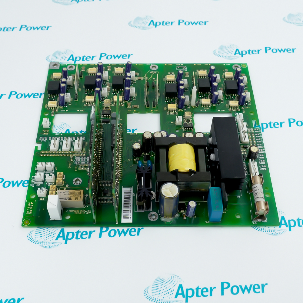
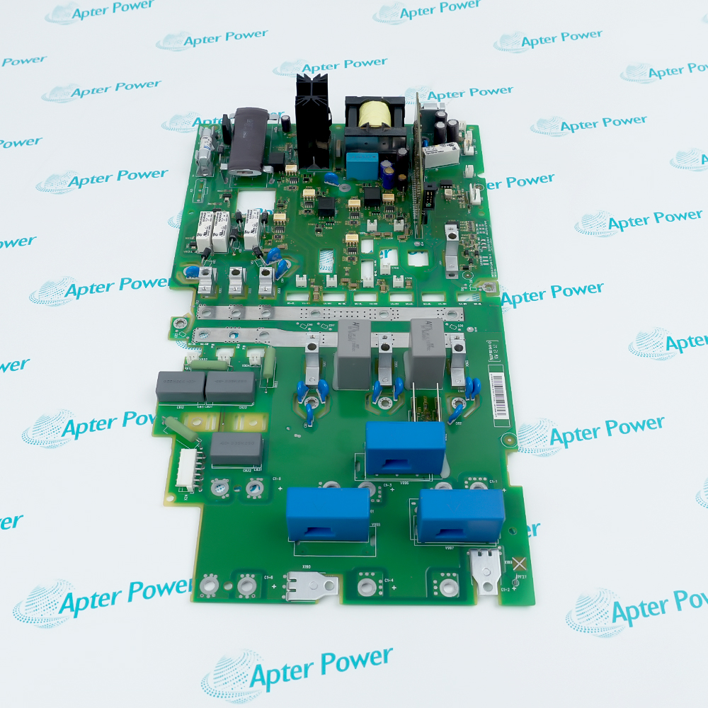
Request board and connector photographs. Have your maintenance team compare the offered RMIO-11C with the drive, software loading package and installed option modules.
Technical specifications for RMIO-11C
-
Manufacturer:ABB
-
Product Category:General Automation
-
Spare Part Number:3AUA0000035408
-
Weight:0.18 kg
-
Tariff Code:8537101190
-
Board execution:Coated
-
Drive voltage class:230–500 V; not control-input voltage
-
Voltage input:1 differential; −10 / 0 / 2 to +10 V
-
Voltage-input impedance:>200 kΩ
-
Current inputs:2 differential; 0 / 4–20 mA
-
Current-input impedance:100 Ω
-
Analog-input isolation:Group isolated; 500 V AC test for 1 min
-
Input common-mode limit:±15 V DC between channels
-
Common-mode rejection:>60 dB at 50 Hz
-
Analog-input inaccuracy:±0.5% FSR at 25 °C
-
Analog-input temperature coefficient:±100 ppm/°C maximum
-
Reference outputs:+10 V, 0 V, −10 V; ±0.5% FSR at 25 °C
-
Reference maximum load:10 mA
-
Reference potentiometer:1–10 kΩ
-
Auxiliary output:24 V DC ±10%; short-circuit protected
-
Shared auxiliary current:250 mA including installed option modules
-
Analog outputs:2 programmable; 0 / 4–20 mA
-
Analog-output load:<700 Ω
-
Analog-output inaccuracy:±1% FSR at 25 °C
-
Analog-output temperature coefficient:±200 ppm/°C maximum
-
Digital inputs:6 programmable plus start interlock
-
Digital input voltage:24 V DC, −15% to +20%
-
Logic thresholds:Low <8 V; high >12 V DC
-
Digital input currents:DI1–DI5: 10 mA; DI6: 5 mA
-
Input filter time constant:1 ms
-
Relay outputs:3 programmable changeover contacts
-
Relay continuous current:2 A rms maximum
-
Relay switching capacity:8 A at 24 V DC / 250 V AC; 0.4 A at 120 V DC
-
Relay minimum current:5 mA rms at 24 V DC
-
Relay isolation test:4 kV AC for 1 min
-
Control power input:24 V DC ±10%
-
Control current consumption:250 mA typical without options; 1,200 mA maximum with options
-
Terminal conductor range:0.3–2.5 mm² / 22–14 AWG
-
Terminal tightening torque:0.2–0.4 N·m
-
Optional optical communication:DDCS through RDCO adapter
Information
- ABB RMIO-11C forms the low-voltage control boundary between an ACS800 application program and the machine wiring. Replacing the board requires the electrical interface, software identity and selected signal assignments to agree.
Supply continuity: An approved external control supply can retain communication while drive input power is absent.
Circuit separation: Analog groups, digital commons and relay contacts have different isolation arrangements.
The standard RMIO interface provides a differential voltage input, two differential current inputs, two current outputs, six programmable digital inputs, a separate start-interlock input and three relays. Factory-macro assignments illustrate one application; a different program can change the purpose of a terminal without changing its printed designation.
Analog inputs share group isolation. Digital input commons can be joined or separated through the specified jumper arrangement, while relay contacts have a different isolation boundary. External 24 V operation, option-module loading and the drive grounding design must be reviewed together; keeping the control electronics alive does not prove that the power stage is ready or safe to operate.
RMIO-11C Official RMIO Hardware Excerpt
Original English ACS800 RMIO chapter: external supply, factory-macro wiring, electrical ratings and isolation. These are shared RMIO interfaces, not a preloaded RMIO-11C application configuration. PDF · 8 pages.RMIO-11C Installation & Verification Guide
Apter Power replacement guide covering software identity, safe isolation, terminal transfer and functional acceptance. PDF · 5 pages.
Application scope: The applications below concern drive-control interfaces and service continuity. They do not establish a motor-power rating, a functional-safety certification or universal compatibility with every ACS800 variant.
Analog speed and process references
Connect suitable voltage or current sources and configure the intended range, scaling and control selection.Discrete machine sequencing
Map start, direction, ramp selection and interlock functions to the installed application instead of assuming factory defaults.Drive status and feedback
Use configured current outputs and relay contacts to send selected drive quantities and states to external control equipment.Maintained control communication
Where designed, use an external control supply and the corresponding software setting to retain communication when drive input power is absent.
Isolate drive input and any external control supply, follow the drive discharge procedure and prove the required safe state before touching the board.
Record the application program, version, parameter backup and option configuration; verify the compatible loading package for the replacement hardware.
RMIO and option modules can share terminal designations. Identify the actual board and signal destination before transferring each conductor.
Retain the approved analog reference, digital common jumper and shielding design; do not bridge isolated groups casually.
Use the specified conductor range and terminal torque. Secure an unused internal supply lead so it cannot contact live parts.
Prove scaled references, interlock response, selected outputs and communication under controlled conditions before releasing the drive.
Alternative Names
Technical notes
Factory macro versus installed logic: The displayed wiring example is for the ACS800 Standard Control Program Factory Macro. It does not prove the installed meaning of every digital input or relay; compare actual parameter assignments before reconnecting machine commands.
Software supply boundary: The RMIO-11C spare-part kit 3AUA0000035408 excludes application software. Preserve the required program identity and arrange a compatible loading package before scheduling a replacement.
External power and isolation: An external supply can leave RMIO electronics energized after drive input power is removed. Include both supplies in the isolation plan and distinguish communication availability from power-stage readiness.

FAQ View All FAQ
-
Why might an electrically connected RMIO-11C still fail to restore the previous drive application?The standard spare-part kit does not include application software. Check the supported loading package, application version and restored parameters before diagnosing an I/O fault; a physically correct board is not a complete programmed replacement.
-
How can RMIO-11C remain communicative after the main drive supply has been disconnected?A designed external 24 V control supply can keep RMIO powered. Verify its connection and the applicable control-board-supply setting. Treat this as a separate energized circuit during isolation, and do not interpret communication as proof that the power stage is ready.
-
Why should a 24 V input at 10 V not be accepted as a valid high state on RMIO-11C?The defined low and high thresholds leave an intermediate region: below 8 V is low and above 12 V is high. At 10 V the state is not guaranteed by those thresholds. Measure voltage at the actual input and common under load, then check supply drop and wiring.
-
Can the switching rating of RMIO-11C relays be used as their continuous-current limit?No. Switching capacity and continuous current are different limits, and the DC rating changes with voltage. Compare the real load and switching conditions with both ratings; an 8 A switching figure does not authorize continuous 8 A service.
-
What should be checked if a 20 mA source reads low only when connected to RMIO-11C?The 100 Ω current input contributes a calculated 2 V burden at 20 mA. Add cable drop and any other series loads to the source compliance requirement. Compare the loop under actual load before changing the input calibration or replacing the board.
-
Can every device connected to RMIO-11C draw the full auxiliary-output allowance independently?No. The auxiliary allowance is shared with installed option modules. Add their consumption to the external load and compare the sum with the applicable output budget; keep this separate from the board’s own control-supply input requirement.
-
Why could a terminal copied by number alone produce the wrong function after replacing RMIO-11C?Option modules may repeat RMIO terminal designations, and application macros can reassign signal functions. Trace the board, connector and conductor destination, then verify the actual parameter assignment and controlled response before enabling machine operation.
-
Does a one-point analog test fully establish usable accuracy for RMIO-11C?No. Check range endpoints and intermediate points, the source burden, common-mode conditions and temperature effects. A stable test source at the board may pass while the installed transmitter or reference wiring introduces an error; compare the complete field loop.
Supporting new and legacy automation
-
Please try to be as accurate as possible with your search.
-
We can quote you on 1000s of specialist parts, even if they are not listed on our website.
-
We can't find any results for “”.
Related cases and sourcing guidance
View all case studiesYou May Also Like
Product Browsing History
-
Whatsapp: +86 18030235313
Send us a message. -
sales13@apterpower.com
Complete our online form. -
+86 18030235313
Speak to our team in your native language.