Speak to a sourcing specialist
sales13@apterpower.com
Get a quick price for SR1B-045N-1KC
E-mail *
Mobile *
Company
Content *
Quantity *
Upload (gif, jpg, jpeg, png, bmp, doc, docx, xls, xlsx, ppt, pdf, csv)
For more information on how your data is processed and stored by Apterpower please read our privacy policy

What happens after you enquire

  • 1

    Requirement review

    We review the part number, quantity and delivery requirements and ask for any missing details.
  • 2

    Quotation and availability

    We confirm the proposed item, condition, availability, price and estimated lead time in the quotation.
  • 3

    Order confirmation and dispatch

    Once the quotation and purchasing details are agreed, your contact will coordinate the order and available dispatch information.

Technical specifications for SR1B-045N-1KC

  • Manufacturer:
    Yokogawa
  • Product Category:
    DCS Systems
  • Spare Part Number:
    SR1B-045N-1KC
  • Estimated shipping dimensions:
    13x29.7x35cm
  • Weight:
    7.56 kg
  • Tariff Code:
    8537101190
  • Counliy of origin:
    Japan
  • Module class:
    DCS I/O
  • System scope:
    Legacy Yokogawa CENTUM
  • Installation:
    Backplane I/O position
  • Configuration scope:
    Channel and field-terminal assignment
  • Maintenance method:
    Exact-variant replacement

Information

Overview Manuals Common Applications Product Precautions
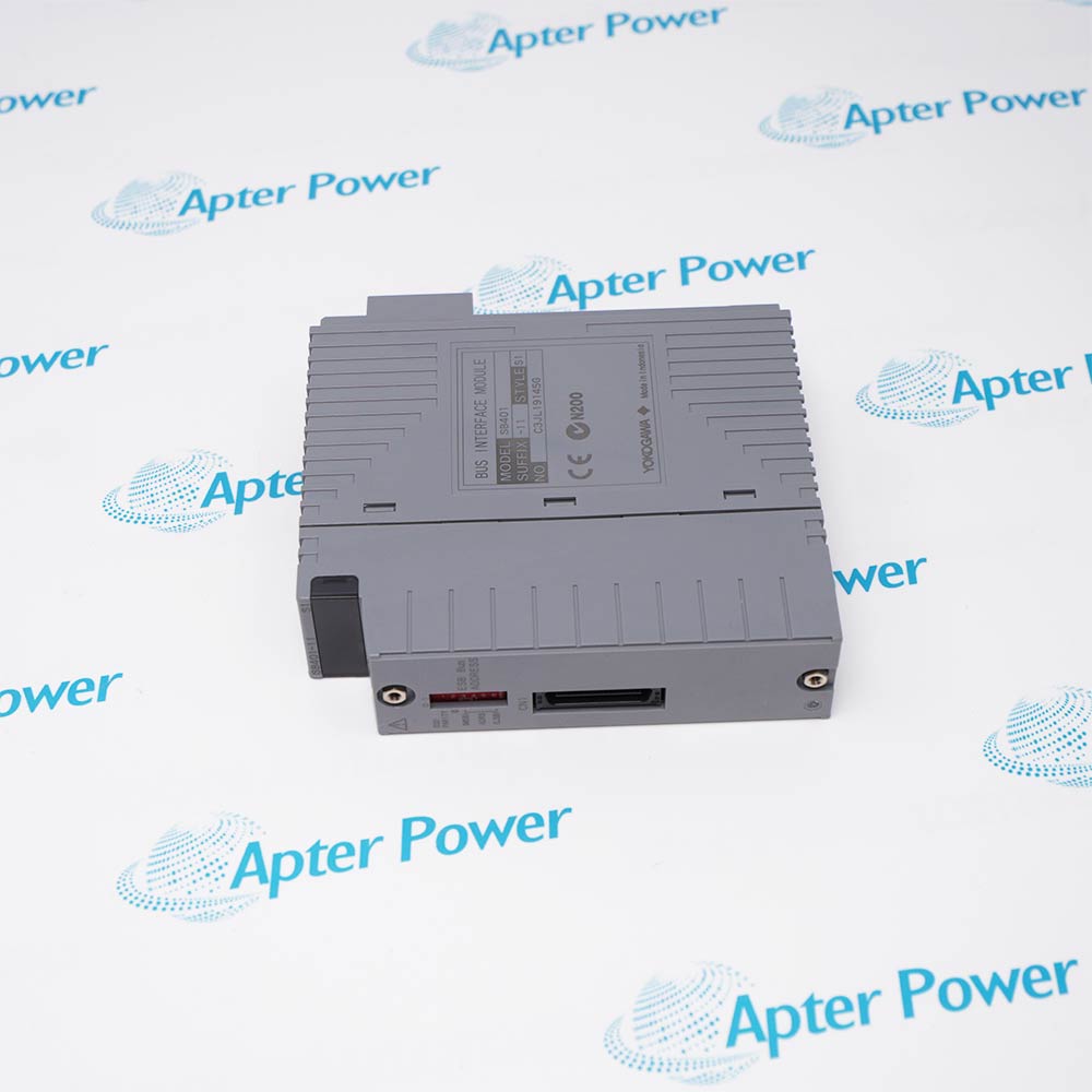
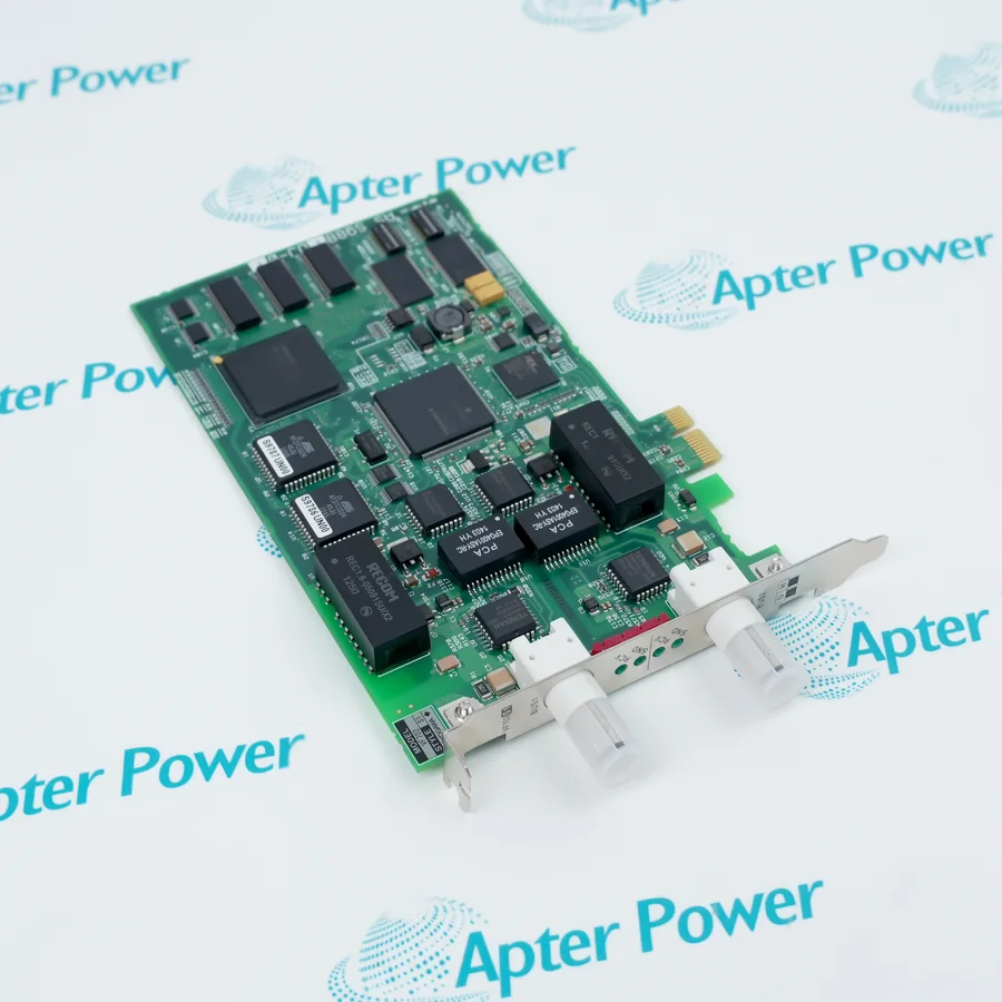
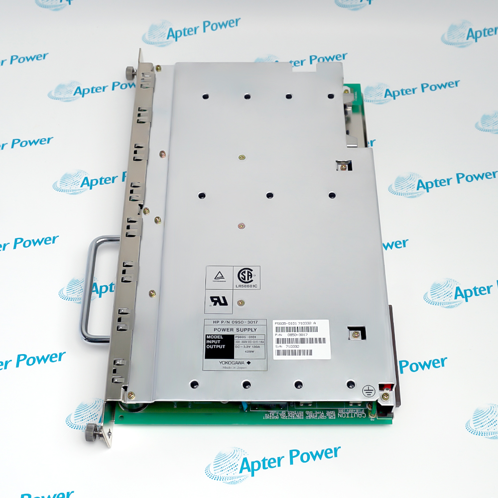
SR1B-045N-1KC forms a backplane-to-field I/O boundary in the assigned station, so channel mapping, terminal wiring and variant identity must be preserved as one maintenance record.
  • Interfaces the installed DCS backplane with assigned field channels.
  • Uses the complete 045N-1KC variant for hardware matching.
  • Retains channel mapping through the station configuration.
  • Requires field-power and terminal assignments to be controlled during service.

SR1B-045N-1KC should be matched to the documented system position, companion hardware and retained project configuration before the channel or station is returned to control.

Important Notice: Preserve the complete SR1B-045N-1KC identity and verify its documented electrical, network or signal response before release.

Yokogawa SR1B-045N-1KC Manuals & Downloads
Yokogawa SR1B-045N-1KC Technical Reference (PDF)Yokogawa SR1B-045N-1KC Installation & Commissioning Guide (PDF)

The first document covers the product function, system role and technical selection. The installation guide covers identification, connection checks, commissioning and the acceptance record.


Legacy DCS I/O repair
Restores the documented field-interface position.
Channel fault isolation
Separates module faults from field wiring and rack power problems.
Maintenance spare control
Keeps an exact variant available for the installed station.
I/O migration survey
Captures channel function and wiring before system modernization.
Before installing Yokogawa SR1B-045N-1KC, confirm the documented system, interfaces and controlled configuration.
1
Confirm the entire SR1B-045N-1KC label.
2
Record every used channel and terminal assignment.
3
Place process loops in the approved maintenance state.
4
Isolate field and rack power before disconnecting hardware.
5
Label commons, shields and external power conductors.
6
Inspect backplane and terminal contacts for damage.
7
Restore the retained channel configuration without copying another module.
8
Test each used point, diagnostics, alarms and interlocks before release.

Technical notes

Preserve the complete SR1B-045N-1KC identity and verify its documented electrical, network or signal response before release.

FAQ View All FAQ

  • What hardware boundary is served by Yokogawa SR1B-045N-1KC?
    It provides the installed DCS I/O interface between the station backplane and assigned field channels.
  • Why must the 045N-1KC portion of Yokogawa SR1B-045N-1KC be retained?
    The complete variant code identifies the installed execution and controls replacement matching.
  • Which records should be captured from Yokogawa SR1B-045N-1KC before removal?
    Capture rack and slot, channel map, terminal numbers, external power, commons, shields and configured signal types.
  • How should field power be treated around Yokogawa SR1B-045N-1KC?
    Identify and isolate every field source separately from rack power before disconnecting the module or terminals.
  • What connector faults can imitate a Yokogawa SR1B-045N-1KC failure?
    Bent contacts, incomplete backplane engagement, loose terminal hardware and damaged cable retention can produce channel or module diagnostics.
  • How is channel configuration restored for Yokogawa SR1B-045N-1KC?
    Load or enter the retained module-specific settings and compare every channel with the approved station record.
  • Which point test is appropriate after fitting Yokogawa SR1B-045N-1KC?
    Exercise each used input or output through its documented operating states while observing controller indication and field response.
  • What final evidence releases Yokogawa SR1B-045N-1KC?
    Normal module diagnostics, correct channel values, verified alarms and successful interlock or output tests complete acceptance.
Related reading

Related cases and sourcing guidance

View all case studies
SPEAK TO OUR TEAM
Let’s find the right solution for you.
Send us the part number, quantity and delivery destination. Our team will help confirm availability and lead time.
  • Whatsapp: +86 18030235313

    Send us a message.
  • sales13@apterpower.com

    Complete our online form.
  • +86 18030235313

    Speak to our team in your native language.