Speak to a sourcing specialist
sales13@apterpower.com

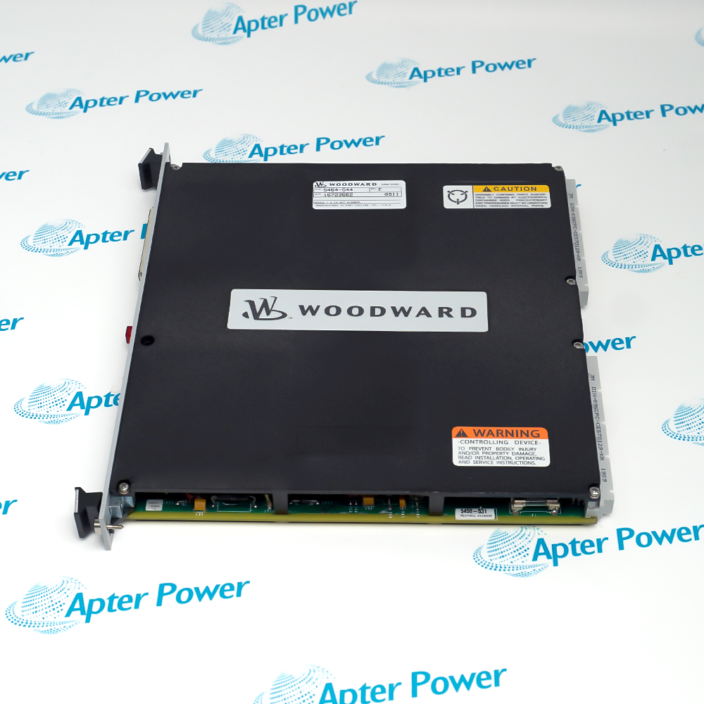
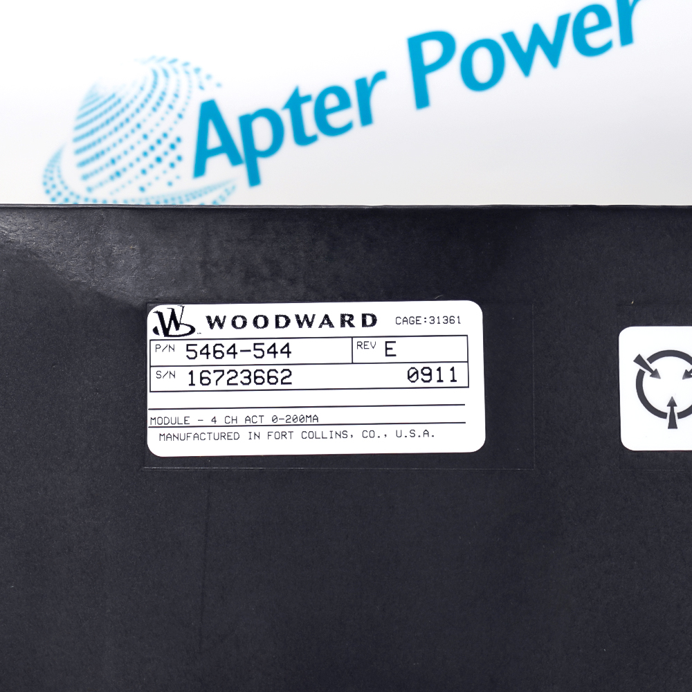
5464-544

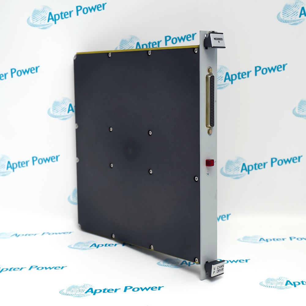
Four-Channel Actuator Driver Module
WOODWARD 5464-544
WOODWARD 5464-544
WOODWARD 5464-544
WOODWARD 5464-544
WOODWARD 5464-544
WOODWARD 5464-544
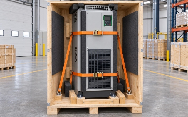
Product image is representative; revision or series may vary. Contact us to request a specific version.

Product Describe:

Woodward 5464-544 converts MicroNet CPU commands into four proportional 0–200 mA actuator outputs. Its channel monitoring supports detection of load and driver faults.
  • Manufacturer part number
    5464-544
  • Shipping
    Swift global dispatch
  • Condition
    New, original product
  • Shipping size (est.)
    2.6cm x 24.6cm x 26.2cm
  • Country of Origin
    USA
Get a quick price for 5464-544
E-mail *
Mobile *
Company
Content *
Quantity *
Upload (gif, jpg, jpeg, png, bmp, doc, docx, xls, xlsx, ppt, pdf, csv)
For more information on how your data is processed and stored by Apterpower please read our privacy policy

What happens after you enquire

  • 0

    Review your reference

    Send the complete 5464-544 reference, label photos and required quantity. Confirm the 5464-544 marking, channel connector arrangement and 0–200 mA execution.

  • 1

    Confirm the offer

    Review the offered execution, condition and included items for 5464-544. Confirm the module and any field termination or cable explicitly itemized in the quotation.

  • 2

    Arrange dispatch

    Swift global dispatch. Confirm quantity, dispatch date and delivery details for 5464-544 in the quotation.

  • Match the complete marking

    Match the complete Woodward 5464-544 marking and installed configuration. Confirm the 5464-544 marking, channel connector arrangement and 0–200 mA execution.

  • Check the offered item before ordering

    Request available label and connector photos. Have your maintenance team compare the offered 5464-544 with the installed equipment and applicable Woodward documents.

Technical specifications for 5464-544

  • Manufacturer:
    WOODWARD
  • Product Category:
    General Automation
  • Spare Part Number:
    5464-544
  • Weight:
    1.04 kg
  • Tariff Code:
    8537101190
  • Actuator channels:
    4
  • Output current range:
    0–200 mA DC
  • Resolution:
    12 bit
  • Accuracy at 25 °C:
    0.1% of full scale
  • Drift:
    150 ppm/°C
  • Maximum actuator resistance:
    45 ohm at 200 mA
  • Maximum actuator inductance:
    1 H
  • Dither waveform:
    25 Hz square wave; amplitude tunable
  • Analog driver bandwidth:
    50 Hz minimum

Information

Overview Downloads Applications / Compatibility Product Precautions
  • Woodward 5464-544 separates the CPU command path from the analog actuator drive stage. Channel output supervision allows the control application to respond to a failed load or driver while retaining the configured shutdown logic.
Command path: VME bus and dual-port memory
Output supervision: Current and voltage monitoring per channel
Fault response: Individually interruptible current drivers
The module scales digital output commands using stored calibration constants and schedules the analog outputs through its local controller. The 5464-544 execution uses the 0–200 mA range; related lower-current actuator variants must not be substituted on the basis of connector fit.

Load capability depends on both actuator resistance and inductance. Check the complete field circuit, including its termination module and cable, against the output envelope before increasing a command. Dither is a tunable actuator-drive function and should be retained from the approved application rather than selected by trial.

A channel or controller fault can interrupt actuator current. Maintenance must account for the resulting actuator position and machine response before testing a channel. Red module indications help distinguish communication loss from an internal fault, but field-circuit checks remain necessary.
Controller platform reference: MicroNet actuator control. Follow the applicable installation instructions and approved design.
Technical and service documents for Woodward 5464-544, separating original engineering information from the installation and verification workflow.
Original manufacturer pages retain their technical context. Use the Apter Power guide with the applicable manufacturer instructions and approved installation design.
System and supply context: Woodward 5464-544 integrates with MicroNet actuator control. Select companion hardware and configured functions for the actual installed arrangement.

Application scope: The applications describe the complete signal or control path. Confirm the intended function and interface; accessories are supplied only when itemized.
Prepare Woodward 5464-544 for its configured installation using these checks.
Secure actuator motion

Identify the four driven functions and their response to current interruption. Establish the approved maintenance state before disturbing CPU communication or field wiring. Record shutdown and enable states for each loop.

Match the field circuit

Trace each actuator through the termination module and cable. Check winding and circuit characteristics against the 200 mA execution and inspect polarity and conductor assignment. Do not substitute a lower-current actuator arrangement.

Retain application settings

Preserve channel scaling, enable logic and dither settings from the approved GAP application. Confirm the module position and configured hardware type before returning power. Avoid introducing a different channel architecture as a service replacement.

Test demand and fault response

Apply controlled commands within the approved test envelope and compare current with actuator response. Investigate load faults and red indications separately. Test current interruption only with the resulting machine state controlled.

Release the closed loops

Remove temporary test conditions in a defined order and verify the final actuator position and process response. Keep the tested command range, faults, adjustments and hardware identity with the maintenance record.

Configuration handover

Retain the final tested settings, physical connection and accepted process response for 5464-544.

Alternative Names

Woodward 5464-544

Technical notes

Current-range identity: Use the 0–200 mA execution for this part number. Do not transfer the resistance rating of the 0–25 mA variant.

Safe fault response: Loss of control communication can interrupt output current. Assess the resulting actuator and machine behavior before testing or removing the module.

Migration boundary: A replacement architecture may require new termination hardware and GAP changes; it is not established by the shared MicroNet family name.


FAQ View All FAQ

  • Why is replacing 5464-544 with a two-channel module an engineering change?
    Channel count, field termination and the control application differ. A migration can require GAP application changes and a revised hardware arrangement.
  • How should a solid red indication on 5464-544 be investigated?
    Check communication between the actuator controller and CPU and the configured module arrangement. Do not assume the indication proves a failed actuator winding.
  • What does a flashing red indication on 5464-544 require?
    It indicates an internal module problem. Put the affected actuator functions in their approved safe state and follow the module replacement and validation procedure.
  • Why does actuator resistance matter at full command from 5464-544?
    The driver must deliver the requested current into the connected load. Include cable and termination contributions when evaluating the specified resistance envelope.
  • Can dither on 5464-544 be changed merely to eliminate actuator noise?
    Retain the approved control settings. Dither affects actuator behavior, so changes require application review and a controlled response test.
  • How should loss of CPU communication be tested with 5464-544?
    Use an approved test plan that accounts for interruption of actuator current and the resulting machine state. Verify the intended shutdown response without exposing the process to uncontrolled motion.
  • Does replacing a like actuator require recalibrating 5464-544?
    The module uses stored calibration and requires no field calibration. Still verify wiring, actuator compatibility and the closed-loop response after replacement.
  • What must be verified before re-enabling a disabled channel on 5464-544?
    Confirm the fault cause is resolved, the load circuit is correct and the commanded response is acceptable. Restore the channel through the approved control application sequence.
Manufacturers

Product Browsing History

Revisit the products you recently viewed on Apter Power.
SPEAK TO OUR TEAM
Let’s find the right solution for you.
Send us the part number, quantity and delivery destination. Our team will help confirm availability and lead time.
  • Whatsapp: +86 18030235313

    Send us a message.
  • sales13@apterpower.com

    Complete our online form.
  • +86 18030235313

    Speak to our team in your native language.