-
Match the complete marking
Match the complete Siemens 6ES5460-4UA12 marking and actual installed configuration. Check both range submodules, both mode-switch blocks and the sensor-front-connector arrangement.
-
Check the offered item before ordering
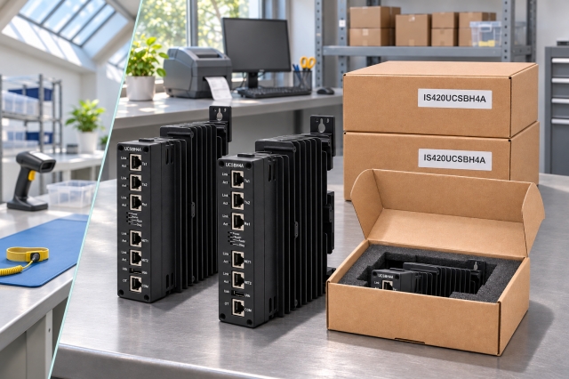
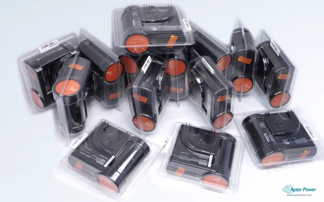
Compare offered-unit photographs, interfaces and included items with the installed 6ES5460-4UA12 and its applicable installation requirements.
Technical specifications for 6ES5460-4UA12
-
Manufacturer:Siemens
-
Product Category:PLC Systems
-
Spare Part Number:6ES5460-4UA12
-
Weight:0.52 kg
-
Tariff Code:8537101190
-
Analog inputs:8
-
Range-module grouping:4 channels per submodule
-
Digital representation:13-bit two’s complement or 12 bits plus sign
-
Conversion method:Integrating dual slope
-
Integration at 50 / 60 Hz:20 ms / 16⅔ ms
-
Coding time at 50 / 60 Hz:60 ms / 50 ms per value
-
Eight-channel cycle at 50 Hz:Approximately 0.48 s
-
Permissible common-mode potential:60 V AC / 75 V DC maximum
-
Low-level range:±12.5 mV with selected gain
Information
- Siemens 6ES5460-4UA12 supports low-level signal acquisition where gain selection and thermal-voltage control matter as much as the nominal transducer range.
Diagnostic workflow: Test-current disable for parallel measurements
Configuration control: Pair range modules with both mode-switch blocks
The selectable gain extends the low-level measuring range. Thermoelectric offsets become particularly significant at these signal levels, so connector condition, compensation arrangements and a stable reference source are important during calibration checks.
The integration setting must suit the mains frequency, and the program must decode the chosen signed-number representation. Validate the complete sensor-to-program path using an appropriate signal source, including the configured overflow and open-circuit response.
6ES5460-4UA12 Original Technical Excerpt
SIMATIC S5 Analog Modules, C79000-B8576-C300-06. Selected original pages retain the relevant technical tables and interface context. PDF · 9 pages.6ES5460-4UA12 Installation & Verification Guide
Apter Power field guide covering capture range and mode settings, check sensor references, reinstate the measurement hardware, validation and handover. PDF · 5 pages.
Application scope: The applications below describe the installed measurement or control path. Select compatible companion equipment; accessories are included only when expressly itemized.
Process-transducer acquisition
Convert the supported current or voltage range to the S5 input word.Resistance temperature measurement
Use the specified Pt100 excitation and reference wiring.Low-level voltage sensing
Match gain, compensation and input submodule to the sensor signal.Analog-loop restoration
Retain hardware range and numerical representation during replacement.
Record the two range-submodule identities, both mode-switch blocks, address and sensor wiring. Identify current-loop, voltage and resistance circuits separately, including any compensation arrangement.
Trace the sensor return and excitation paths. Review the Pt100 or two-wire-transmitter common-reference arrangement and confirm that the actual potential differences remain within the module limits.
Isolate the field circuit as required, then restore the module, submodules and front connector according to the installation procedure. Select the recorded integration frequency and digital representation; verify the gain selection and test-current control wiring.
Apply traceable reference signals at zero and suitable nonzero points. Allow the integrating conversion and channel scan to settle; control thermal offsets and disable test current when making the specified parallel measurement.
Test the supported overflow and open-circuit response with the process secured. Remove temporary signal sources, restore each sensor and record the final range, switch settings and observed diagnostics.
Retain the final 6ES5460-4UA12 identity, tested settings and accepted channel or system response for subsequent maintenance.
Alternative Names
Technical notes
Range hardware: Two four-channel submodules define the electrical input circuits. Verify their part numbers and mode compatibility before connecting a current loop or voltage source.
Sensor-reference boundary: The Pt100 wiring arrangement does not retain isolation between individual inputs. Assess common references and the permitted common-mode voltage for the actual sensor circuit.
Sampling and diagnostics: Disable the open-circuit test current in accordance with the wiring instructions when performing a parallel voltage measurement; otherwise the measuring instrument can affect the diagnostic current path.

FAQ View All FAQ
-
When should the increased gain of 6ES5460-4UA12 be used?Use it only when the intended low-level range and installed submodule require it. Recheck scaling and usable headroom; gain selection is not a general cure for noisy wiring.
-
Why can a voltmeter connected beside 6ES5460-4UA12 distort an open-circuit check?Its parallel current path can interact with the diagnostic test current. Use the designated test-current-disable arrangement before interpreting the measurement.
-
What makes connector temperature gradients significant for 6ES5460-4UA12?Thermoelectric junction voltages can be material compared with a millivolt-level signal. Keep connections stable and assess compensation before correcting an apparent offset in software.
-
How should a zero offset be separated from a range error on 6ES5460-4UA12?Apply a suitable zero reference and at least two nonzero points. Check gain, submodule and wiring first; a single-point adjustment cannot establish the full conversion slope.
-
Can all inputs of 6ES5460-4UA12 use different ranges independently?The hardware is organized around four-channel submodules and module mode settings. Verify permitted range combinations rather than assuming per-channel software programmability.
-
Why can a disconnected Pt100 current lead appear as zero on 6ES5460-4UA12?A break in an excitation-current lead can produce a zero digital value. Validate the complete RTD circuit and diagnostic behavior instead of interpreting zero as a healthy sensor.
-
What must be reviewed before enabling open-circuit detection on 6ES5460-4UA12?Confirm that the selected measurement range supports the function and that the chosen group and sensor wiring match the diagnostic settings.
-
How should 6ES5460-4UA12 be accepted after a low-level input repair?Compare stable reference points through the full configured range, verify sign and compensation, then test the intended wire-break response without leaving temporary test wiring in place.
Supporting new and legacy automation
-
Please try to be as accurate as possible with your search.
-
We can quote you on 1000s of specialist parts, even if they are not listed on our website.
-
We can't find any results for “”.
Related cases and sourcing guidance
View all case studiesYou May Also Like
Product Browsing History
-
Whatsapp: +86 18030235313
Send us a message. -
sales13@apterpower.com
Complete our online form. -
+86 18030235313
Speak to our team in your native language.