Speak to a sourcing specialist
sales13@apterpower.com

PCD2.C100

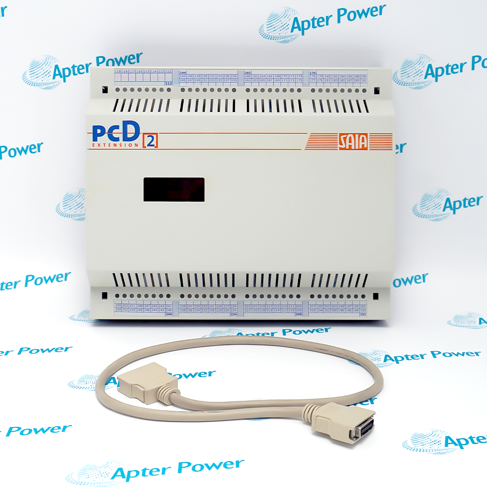
PCD2 Eight-Socket I/O Expansion Housing
SAIA PCD2.C100 (1)
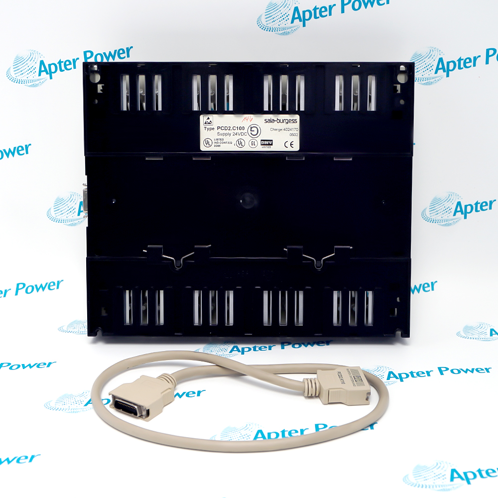
SAIA PCD2.C100 (2)
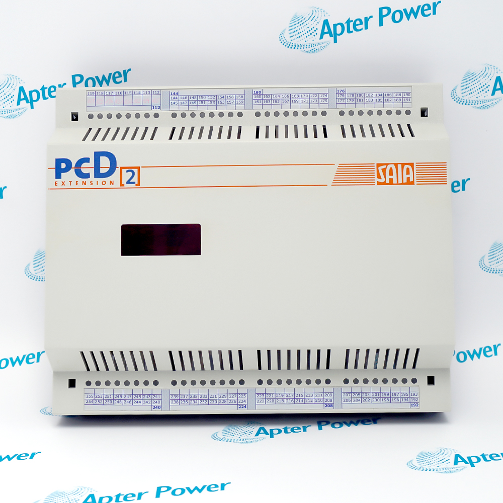
SAIA PCD2.C100 (3)
SAIA PCD2.C100 (1)
SAIA PCD2.C100 (2)
SAIA PCD2.C100 (3)
Product image is representative; revision or series may vary. Contact us to request a specific version.

Product Describe:

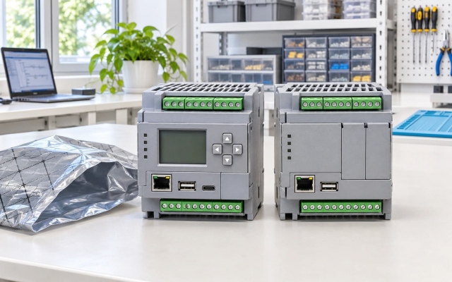
SAIA PCD2.C100 is an eight-socket expansion housing for compatible PCD2.Mxx0 controllers. A 26-core extension cable connects the base unit to additional I/O module positions.
  • Manufacturer part number
    PCD2.C100
  • Shipping
    Swift global dispatch
  • Condition
    New, original product
  • Shipping size (est.)
    24.8cm × 6cm × 20.8cm
  • Country of Origin
    Switzerland
Get a quick price for PCD2.C100
E-mail *
Mobile
Company
Content *
Quantity *
Upload (gif, jpg, jpeg, png, bmp, doc, docx, xls, xlsx, ppt, pdf, csv)
For more information on how your data is processed and stored by Apterpower please read our privacy policy

What happens after you enquire

  • 0

    Review your reference

    Send the complete PCD2.C100 marking, PCD2 CPU model, module list, cable arrangement and required quantity.

  • 1

    Confirm the offer

    Review housing condition, module and cable scope, offered quantity and dispatch date in the quotation.

  • 2

    Arrange dispatch

    Confirm the accepted quantity and destination for shipment arrangements.

  • Match the complete marking

    Match the full PCD2.C100 housing marking, base controller, extension cable and planned eight-socket map before ordering.

  • Check the offered item before ordering

    Request photos of the offered PCD2.C100 and have your maintenance team compare them with the installed housing and applicable Saia PCD1 / PCD2 documentation before ordering.

Technical specifications for PCD2.C100

  • Manufacturer:
    SAIA
  • Product Category:
    PLC Systems
  • Weight:
    0.6 kg
  • Tariff Code:
    8537101190
  • I/O module sockets:
    8
  • Expansion socket range:
    8–15, clockwise
  • Base CPU socket range:
    0–7, clockwise
  • Bus cable conductors:
    26
  • Below-mounted cable:
    PCD2.K100 · 0.5 m
  • Below-mount spacing:
    Maximum 150 mm
  • Side-by-side cable:
    PCD2.K110 · 0.7 m
  • Special-use cable:
    PCD2.K120 · 2 m; specified applications
  • W/H restricted socket:
    15 (W and H modules excluded)
  • Illustrated base CPUs:
    PCD2.M120 / M150 / M170 / M480

Information

Overview Downloads Applications / Compatibility Product Precautions
  • The PCD2.C100 adds module positions to a compatible PCD2 controller while the base CPU remains responsible for control and I/O processing. Plan its cable route and module population before fitting the housing.
Expansion role: Eight additional physical PCD2 I/O sockets
Bus link: 26-core cable to the PCD2.Mxx0 base unit
Slot planning: Positions 8–15 with a W/H limit at socket 15
The PCD2.C100 provides eight I/O positions in a housing with the same physical envelope as the PCD2.Mxx0 base family. Its sockets continue the numbering of the base controller: the base positions are 0–7 and the expansion positions are 8–15. The installed CPU and its permitted expansion arrangement still determine the usable module count and configuration.

A 26-core bus-extension cable joins the expansion housing to the base. The PCD2.K100 is described for a beneath-each-other layout and the PCD2.K110 for a side-by-side layout. The PCD2.K120 is a 2 m option for specified applications, so its suitability should be checked against the installed controller and cabinet route rather than assumed from length alone.

Module planning must respect the socket map. In the PCD2.C100, socket 15 is not available for W or H module types; T8xx modem placement has separate restrictions. Map each existing I/O address and module type to the intended socket, then verify cable seating, controller recognition and live I/O behavior in a controlled acceptance test.
Controller platform reference: SAIA PCD2.Mxx0 controller and expansion system. Check the installed CPU and socket plan.
Use the original Saia PCD1 / PCD2 manual excerpt for the expansion housing, cable and socket map. The Apter Power field guide organizes mounting, I/O mapping, controlled tests and handover.
Apply the manufacturer instructions and the site-approved control design for installation and maintenance.
Prepare SAIA PCD2.C100 using the applicable installation instructions and site isolation procedure.
Isolate the controller

De-energize the installed PCD2 system and follow the cabinet isolation procedure before mounting or reseating the bus link.

Check the exact housing

Verify PCD2.C100 on the label; PCD2.C150 is a four-position variant with a different capacity.

Select the bus cable

Use the cable arrangement specified for the mounting orientation and controller; keep the 26-core link fully seated.

Respect socket 15

Do not place a W or H module in PCD2.C100 position 15; review separate restrictions for T8xx modems.

Map the I/O program

Compare physical positions 8–15 with address assignments, terminal labels and the saved controller project.

Prove each channel

After controlled power-up, verify controller recognition, input state and output response one channel group at a time.

Alternative Names

PCD2 C100 SAIA PCD2-C100

Technical notes

System scope: The PCD2.C100 is an expansion housing; its usable module mix depends on the installed PCD2 CPU and slot restrictions.

Cable and position: The base-to-expansion link uses a 26-core cable; socket 15 excludes W and H modules.

Technical reference: Saia-Burgess Controls PCD1 / PCD2 Series Manual, 26/737 EN24.

FAQ View All FAQ

  • How is PCD2.C100 distinguished from PCD2.C150 in a retrofit?
    Read the full housing label and count positions: PCD2.C100 has eight expansion sockets, whereas PCD2.C150 has four. Reconcile the cabinet layout, bus cable and controller project before substituting either housing.
  • Which cable should connect PCD2.C100 beneath its base controller?
    The manual shows PCD2.K100 for an under-mounted PCD2.C100. Confirm the actual base-controller model, cable route and mating connectors before energizing the assembly.
  • Which cable should connect PCD2.C100 beside its base controller?
    The manual shows PCD2.K110 for the side-by-side arrangement. Check orientation and cable seating, then verify that the CPU recognizes the intended expansion positions.
  • When can PCD2.K120 be used with PCD2.C100?
    PCD2.K120 is a 2 m cable described for specific applications. Confirm that the installed PCD2 controller and intended layout are covered by those application instructions before selecting the longer link.
  • Why can a W or H module fail in PCD2.C100 socket 15?
    The PCD2.C100 socket map excludes W and H types from position 15. Move the module to an allowed position, update the controller project and retest its channel mapping.
  • How should PCD2.C100 positions be addressed in the controller project?
    The base PCD2.Mxx0 sockets are 0–7 and the PCD2.C100 sockets continue 8–15. Compare the actual module order with the saved I/O map and terminal schedule before any functional test.
  • Can a T8xx modem be installed in any PCD2.C100 socket?
    No unrestricted placement is established. The series manual points to separate T8xx modem instructions; check the particular modem type and permitted position before fitting it.
  • What evidence should be kept after commissioning PCD2.C100?
    Record the complete housing and CPU labels, cable model and orientation, module-by-socket map, project revision, controller recognition and channel test results. Investigate any mismatch before returning the system to service.
SPEAK TO OUR TEAM
Let’s find the right solution for you.
Send us the part number, quantity and delivery destination. Our team will help confirm availability and lead time.
  • Whatsapp: +86 18030235313

    Send us a message.
  • sales13@apterpower.com

    Complete our online form.
  • +86 18030235313

    Speak to our team in your native language.