
Bently
View products



Two PowerFlex 7000 spare references share a 56 V designation but serve different stages of the drive's supply chain. The 80026-529-01-R is an AC/DC power unit; the 80026-044-06-R is an IGDPS. Fault evidence and the full installed part number should guide the spare enquiry.
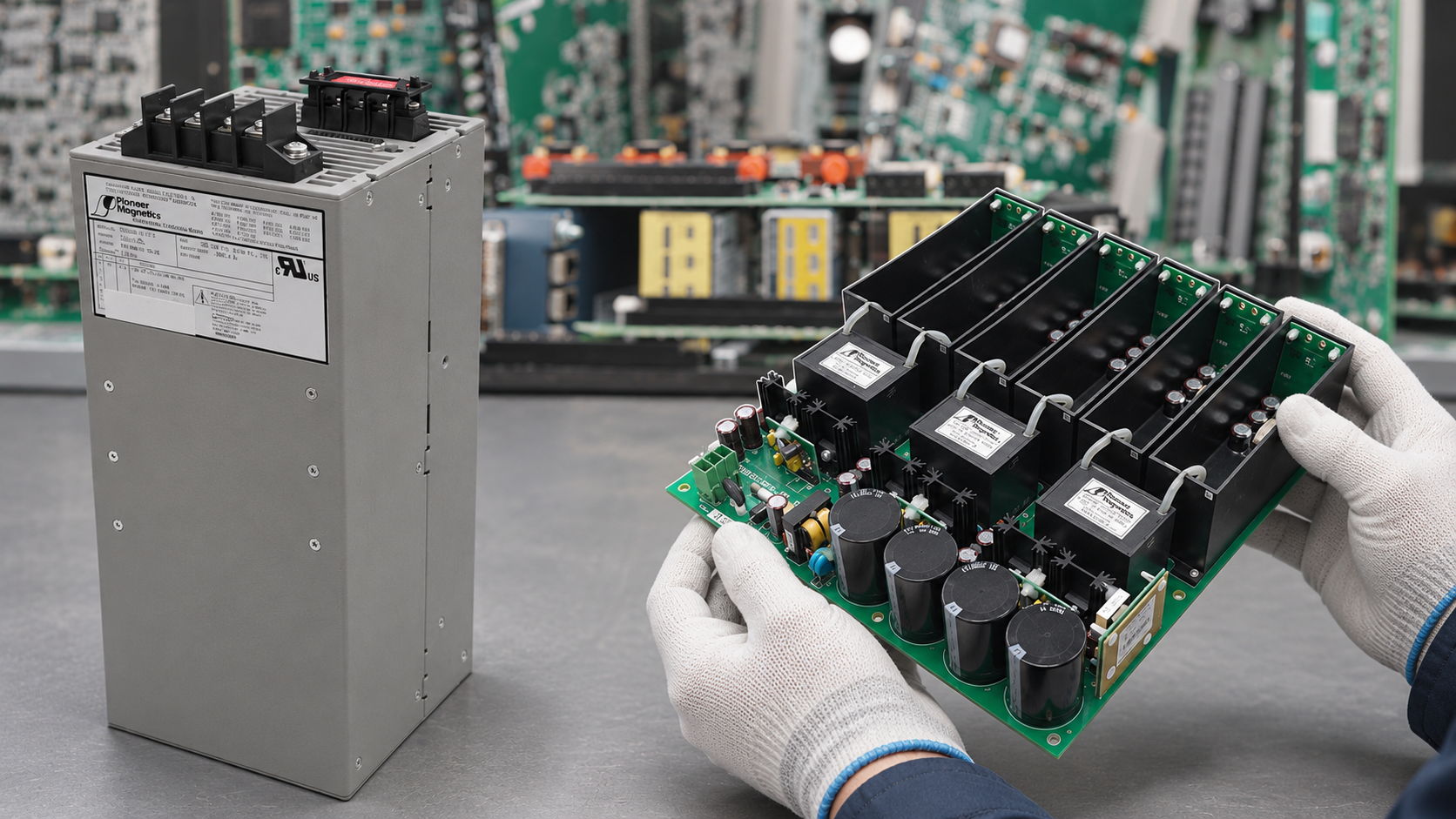
80026-529-01-R is the 1,000 W AC/DC supply with a 56 V DC output. 80026-044-06-R is a separate IGDPS listed as 56 V DC / 20 V DC.
The PowerFlex 7000 troubleshooting guide lists both references in its spare-parts appendix under power supplies. It describes 80026-529-01-R as a single-phase-input AC/DC unit that produces 56 V DC at a 1,000 W rating. It lists 80026-044-06-R as an IGDPS with a 56 V DC / 20 V DC designation. This is a functional distinction, not a choice between two wattages of one interchangeable supply.
For fault isolation, engineers should establish where the expected voltage is lost. A missing or unstable 56 V DC feed calls for checks upstream of the IGDPS, including the AC/DC supply, its input, protection and connections. If the 56 V DC stage is present but the relevant downstream supply is absent, the IGDPS and its wiring become a different investigation. A symptom alone does not establish that either component has failed: a fault elsewhere, a loose connection or another power-chain component can produce a similar indication.
The troubleshooting guide distinguishes the monitored AC input, the 56 V DC output and the two downstream 56 V feeds. The fault number helps identify which part of the path needs investigation.
| Fault | Indication | Diagnostic meaning |
|---|---|---|
| 58–61 | AC/DC #1–#4 AC Fail AC input |
Reported when a monitored supply input falls below 85 Vrms in the guide. |
| 48–51 | AC/DC #1–#4 DC Fail DC output |
Reported when a monitored output falls below 49 V DC. |
| 52 | Control 56V Loss | Loss of the 56 V feed to the DC/DC converter. |
| 53 | IGDPS 56V Loss | Loss of the 56 V feed to the IGDPS. |
A drive may have more than one numbered AC/DC supply, so the number in the message matters. These thresholds describe the drive's monitoring; they are not a stand-alone acceptance test for a loose spare or a substitute for the installed drive's drawings.
For code 53, the guide directs technicians to examine connections, the AC/DC converter output and the voltage entering the IGDPS; it also describes comparing the measured value at ACB connector J15 with the processor's P101 reading. A code 53 report does not by itself identify a defective 80026-044-06-R. An upstream supply problem, wiring fault or measurement path can produce the reported loss. Record the exact message and readings before resetting the drive, then follow the service procedure for that installed configuration.
The spare-parts appendix lists three distinct single-phase AC/DC units with a 56 V DC output. Their complete references and power ratings differ:
Different component: 80026-044-06-R. IGDPS, listed as 56 V DC / 20 V DC; it is not another AC/DC wattage option.
The common 56 V designation does not establish interchangeability. Selection needs the complete installed reference, electrical role, mechanical arrangement, connector layout and approved equipment documentation. Do not substitute a different power rating or revision solely because it appears to fit or carries a 56 V label.
Preserve the drive model and frame information, the fault history, the location of the numbered supply, photographs of the complete product label, connector positions and relevant wiring references. For a suspected IGDPS problem, document whether the incoming 56 V feed was present at the point specified by the site drawing; any downstream checks must use the test locations and limits for that drive. Measurements and work inside a medium-voltage drive belong to qualified personnel following the site's isolation and verification procedure.
After an approved replacement is installed, check seating and connections against the recorded configuration, restore control power under the authorized procedure and compare the drive's monitored values and alarms with the pre-change record. Confirm that the original fault does not recur during the prescribed verification sequence. If the fault persists, continue diagnosis of the supply path, wiring and sensing circuitry rather than repeatedly exchanging modules. The aim is evidence of a corrected fault in the installed system, not simply a powered-up replacement unit.
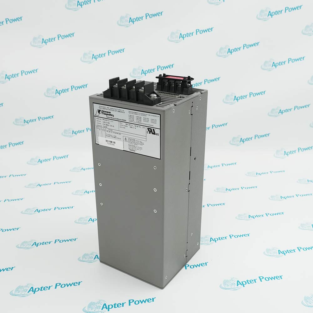
Confirm the complete reference on the installed unit, the input arrangement, output rating, connector layout and physical mounting. The archive photograph depicts a related 80026-529-01 power unit; the exact -R suffix must be checked from the original item label before an offer is approved.
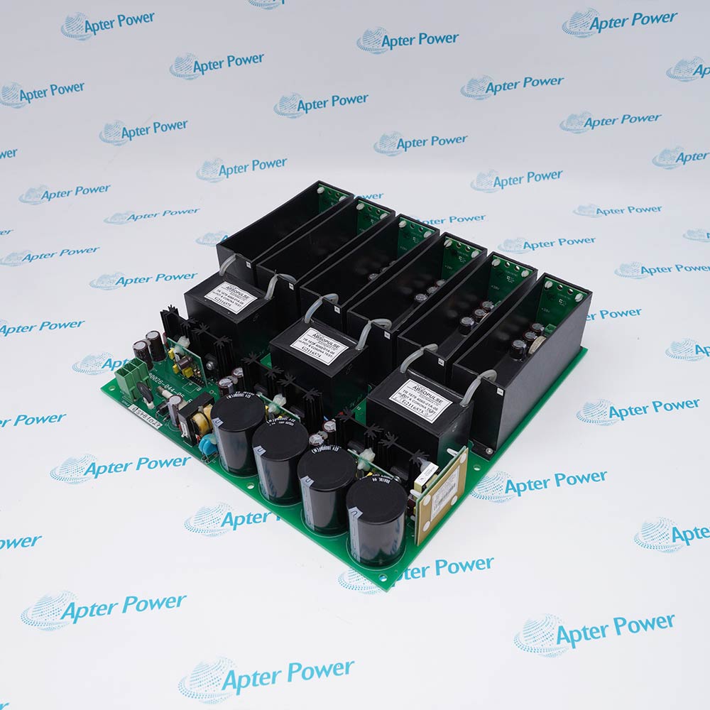
The photographed assembly shows the IGDPS board architecture and multiple power sections. Review the original label and board marking for the exact ordered revision and suffix. A visually similar board is not enough evidence of interchangeability.
When sending an enquiry, include the installed drive's full catalog reference and frame or configuration details, photographs of the failed unit's labels and connectors, and any applicable drawing or service record. This helps distinguish a complete AC/DC supply from an IGDPS assembly and prevents a procurement request written only as “PowerFlex 7000 power supply” from reaching the wrong stage. For the purchasing steps, see how to order.
Apter Power's Allen-Bradley parts range provides a starting point for related components. The site's technical resources and part-verification guidance can help organize the details for a precise request.
No. The spare-parts list assigns the first to a 56 V DC, 1,000 W AC/DC supply and the second to a 56 V DC / 20 V DC IGDPS. Their roles and physical interfaces must be assessed separately.
No. Verify the input, output, protection, connections and other relevant components using the installed drive's service documentation before isolating the cause.
Confirm the exact label and suffix, installed drive configuration, board revision, connector arrangement and the scope of the offered assembly. Have the site engineer approve any proposed difference.
No. They show related physical product examples from Apter Power's archive. The exact order code on the individual offered item should be confirmed from its original label photographs.
Send both part references, the drive catalog number, quantity, readable label photos and your required delivery date. Apter Power can review the requested supply scope and quotation details.
Contact Apter PowerTel: +86 18030235313 · Email: sales13@apterpower.com
Apter Power is an independent supplier. Allen-Bradley, PowerFlex and Rockwell Automation are trademarks of their respective owners. This article is an independent spare-planning update, not a manufacturer announcement. Technical figures above were checked against the manufacturer's PowerFlex 7000 troubleshooting guide; site-specific service decisions require the applicable drive documentation.


Share your parts list, quantities and required date.
Email your parts list




