
Bently
View products



An ABB CI858K01 spare should be checked as a complete DriveBus interface package—not only as a removable communication module. The orderable kit CI858K01 / 3BSE018135R1 combines the CI858 communication interface with its TP858 60 mm baseplate. For a useful maintenance spare, teams should also record the optical network layout, NDBU branching hardware, CEX-Bus position and the exact controller configuration that the interface serves.
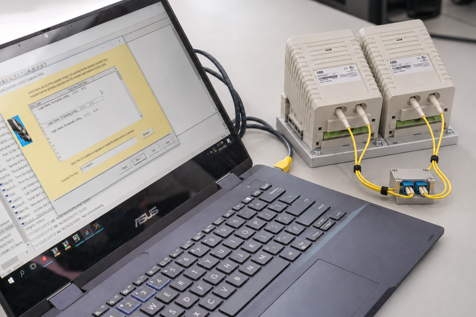
The test scene places CI858K01 beside the engineering workstation and optical connections rather than presenting it as an isolated spare. Exact supplied contents, revision and condition are still confirmed against the specific enquiry.
CI858 provides the DriveBus communication function between an AC 800M controller and ABB drives or supported special I/O. The interface receives power from the controller through the CEX-Bus, so it does not require a separate external module supply. However, that functional description does not define everything required for a physical replacement.
| Item to verify | Confirmed function or scope | Why it matters for a spare |
|---|---|---|
| CI858K01 3BSE018135R1 |
Orderable DriveBus interface package | The enquiry should state the full kit identity rather than using “CI858” as a generic description. |
| CI858 | Communication interface mounted on the CEX-Bus baseplate | The removable interface alone is not the same supply scope as a complete CI858K01 package. |
| TP858 | 60 mm baseplate supplied in the CI858K01 package | Baseplate condition, code lock, connectors and DIN-rail mounting should be checked when the site needs a complete spare. |
| DriveBus path | Optical communication from CI858 to ABB drives or supported special I/O | The failed item may be the interface, optical lead, branching unit or a topology issue; replacing the module alone does not isolate every fault. |
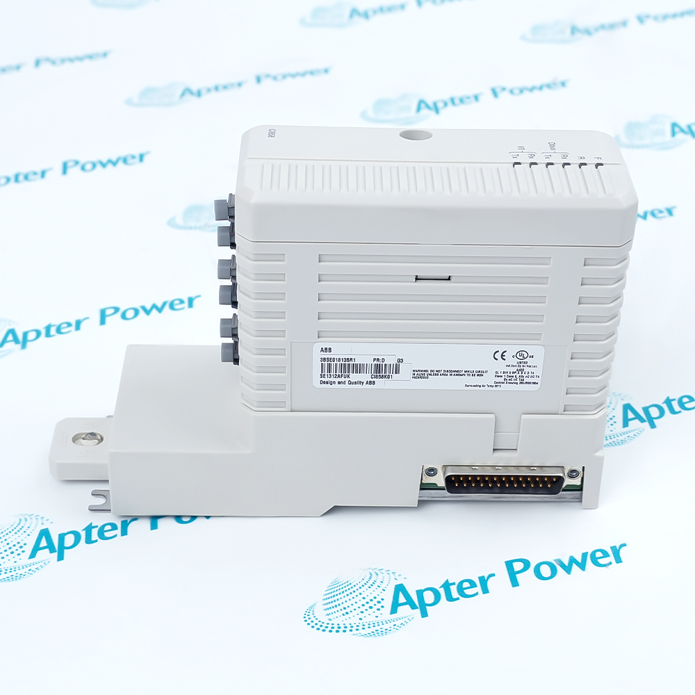
Record CI858K01, 3BSE018135R1, hardware revision and the identity of the mounted baseplate. A request written only as “CI858” may be interpreted as the removable interface rather than the complete CI858K01 package. State whether the requirement is the full CI858 plus TP858 kit, a module-only spare or a verified combination.
CI858 operates as the DriveBus master at 8 Mbit/s. The interface uses an optical connector and supports hot swap, but the published architecture does not provide line redundancy or module redundancy for CI858. A maximum of 24 ABB drives can be connected to one CI858, and a maximum of two CI858 interfaces can be connected to one AC 800M controller.
When more than one drive is connected, an ABB NDBU branching unit is used to create a logical bus with a physical star topology. Branching units can be chained, which makes the installed layout important: an intermittent optical branch, contaminated connector, damaged fibre or incorrect reconnection can look like an interface problem even when the CI858 itself is serviceable.
Specify CI858K01 / 3BSE018135R1 and state whether the complete CI858 plus TP858 package is required. Do not assume a listing or photograph proves which accessories are included.
Inspect the TP858 housing, code lock, CEX-Bus connection, DIN-rail latch and optical connector area. A sound interface module does not compensate for a damaged or incompatible mounting base.
Record every fitted optical lead, destination, branch and NDBU position. Note connector condition, bend radius, labels and any repeated communication faults before disturbing the network.
Capture the AC 800M controller reference, CEX-Bus order, adjacent modules and terminator arrangement. Confirm how many CI858 interfaces are installed and which drive group each one serves.
Retain the current project, hardware configuration, drive node information, relevant tool versions and a verified recovery point. Hardware availability without recoverable configuration is not complete readiness.
Agree what can be checked before shipment and what must be validated in the target system. Do not claim network compatibility, firmware suitability or plant operation without the site-specific evidence.
CI858 is designed with hot-swap capability, but that statement should not be converted into a blanket instruction to remove a module from a running plant. The actual decision depends on the controller state, drive process, network condition, installed firmware, site procedure and the consequences of losing DriveBus communication. The maintenance plan should define who authorises the intervention, what equipment must be placed in a safe state and how communication recovery will be proved.
Before removal, label and photograph the optical connections, confirm the replacement identity, preserve the current configuration and record diagnostic indications. After installation, verify module recognition, DriveBus communication, expected drive nodes, alarms and the operating state of every affected section. If the fault remains, continue the investigation through the fibre route, NDBU branches, connectors and configuration rather than repeatedly exchanging the interface.
Teams building a wider AC 800M spare plan can review the Apter Power ABB parts range, organize manuals through Technical Resources, and use the part-verification guide to prepare clear label evidence.
CI858K01 / 3BSE018135R1, quantity, readable label photographs, hardware revision and whether CI858 plus TP858 are both required.
AC 800M controller reference, CEX-Bus position, number of CI858 modules, connected drive count and NDBU branching arrangement.
Acceptable condition, destination, required-on-site date and any documentation or inspection photographs needed before dispatch.
CI858K01 is the orderable DriveBus interface package containing the CI858 communication interface and the TP858 60 mm baseplate.
No. CI858 identifies the communication interface function or removable module, while CI858K01 identifies the package that includes CI858 together with the TP858 baseplate. The requested scope should be written explicitly.
The published maximum is 24 ABB drives per CI858. The actual project configuration, node arrangement and process requirements must still be checked for the installed system.
When more than one ABB drive is connected to CI858, an NDBU branching unit is used to form the physical star arrangement for the logical DriveBus. Chained branching units and every optical branch should be documented.
No. CI858 is specified without line redundancy and without module redundancy. Spare strategy and recovery planning should reflect that architecture.
CI858 supports hot swap, but removal from a live system must follow the site's approved procedure and risk assessment. Hot-swap capability does not prove that a specific process can tolerate loss and recovery of DriveBus communication.
Reconfirm the exact hardware and CEX-Bus position, module recognition, optical port assignment, fibre condition, NDBU branches, drive nodes, configuration and diagnostic indications. Do not assume a second interface exchange will solve a network or configuration fault.
Send the full model, quantity, label photographs, required supply scope, installed controller details, destination and required-on-site date. Apter Power will use the submitted information for product and quotation review; final system compatibility remains the responsibility of the user and project engineer.
Contact Apter Power
Share your parts list, quantities and required date.
Email your parts list




