Get Parts Quote
Name
Company *
Phone *
Email *
Address
City
State / Province / Region
Zipcode
Country
Quantity *
Part Number *
Manufacturer
Preferred Condition
Additional Information
Cancel

9753-110

Pulse Input / Pulse Totalizer Termination Panel
In Stock
Ships by Tuesday, September 22
Fast Shipping Available

Product Describe:

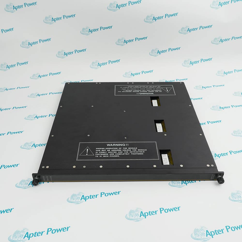
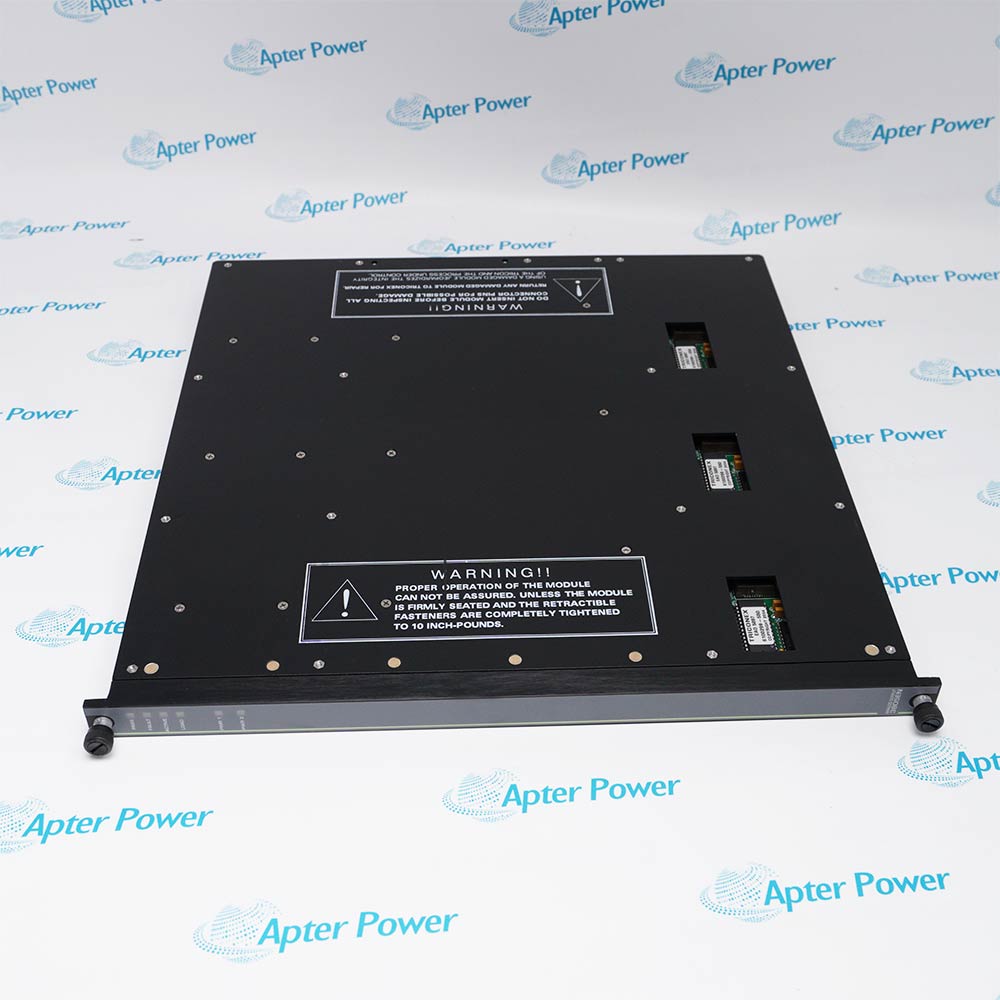
Triconex 9753-110 is a basic termination panel for pulse-input and pulse-totalizer modules. It routes field pulse signals to the selected Tricon processing module.

Ask our team:

Get a quick price for: 9753-110
Quantity*
Upload (gif, jpg, jpeg, png, bmp, doc, docx, xls, xlsx, ppt, pdf, csv)
For more information on how your data is processed and stored by Apterpower please read our privacy policy.

Technical specifications for 9753-110

Technical specifications for 9753-110

  • Manufacturer:
    Invensys
  • Product Category:
    DCS System
  • Spare Part Number:
    9753-110
  • Estimated shipping dimensions:
    12.5x10.9x7.8cm
  • Weight:
    0.3 kg
  • Tariff Code:
    8537101190
  • Counliy of origin:
    USA
  • Panel type:
    Basic
  • Pulse-input points:
    8
  • Pulse-totalizer points:
    16
  • Pulse-input terminals:
    Differential IN+ / IN-
  • Compatible PI modules:
    3510; 3511
  • Compatible PTI module:
    3515
  • 3510 frequency / update:
    20 Hz to 20 kHz / 50 ms typical
  • 3511 frequency / update:
    20 Hz to 20 kHz / 25 ms typical
  • 3515 frequency:
    0 to 1 kHz
  • 3515 module points:
    32
  • Panel width:
    3 in (7.62 cm)
  • Panel length:
    5 in (12.7 cm)
  • Panel height:
    4.25 in (10.795 cm)
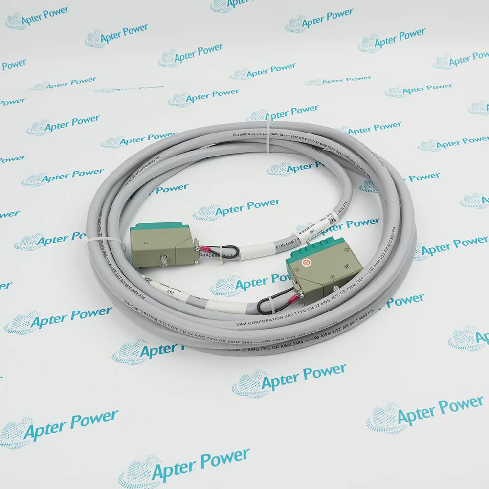
  • Associated cable:
    4000103-510

Information

Information

Overview Manuals Common Applications Product Precautions
Triconex 9753-110 is a basic termination panel for pulse-input and pulse-totalizer modules. It routes field pulse signals to the selected Tricon processing module.
  • Terminates eight balanced pulse-input channels from magnetic speed sensors
  • Reconfigures as a sixteen-point field interface for the 3515 pulse totalizer module
  • Carries differential IN+ and IN- conductors to the selected Tricon input module
  • Provides panel-level labeling for the assigned pulse or totalizer channel range

9753-110 installs with 3510 or 3511 pulse-input module, 3515 pulse-totalizer input module, 4000103-510 backplane cable, shielded twisted-pair field wiring in an engineered Tricon v9-v10 field termination configuration.

The commissioning workflow covers installed-hardware matching, controlled start-up and functional verification for this pulse input / pulse totalizer termination panel.

Important Notice: Confirm the complete 9753-110 marking, installed-system configuration, field connections and controlled functional test before commissioning or replacement.

Apter Power 9753-110 Manuals and Guides
Apter Power 9753-110 Product Technical Reference PDFApter Power 9753-110 Installation and Verification PDF
The first document is an Apter Power model-specific technical reference. The second supports model-specific installation, configuration and engineering verification.
Turbine and compressor magnetic speed pickup terminationSupports turbine and compressor magnetic speed pickup termination through the installed pulse input / pulse totalizer termination panel in a configured Tricon system.
High-frequency rotating-equipment pulse measurementUses 9753-110 for high-frequency rotating-equipment pulse measurement after the assigned host module, field interface and channel mapping are confirmed.
Thirty-two-point pulse-totalizer field terminationApplies the 9753-110 hardware arrangement to thirty-two-point pulse-totalizer field termination with controlled wiring and signal verification.
Tricon pulse-channel retrofit and loop verificationProvides a defined engineering path for tricon pulse-channel retrofit and loop verification, including installation checks and final functional proof.
Read the applicable Triconex installation instructions before work. Verify 9753-110 and the installed Tricon v9-v10 field termination configuration.
1Verify 9753-110 and the selected PI or PTI duty before moving field conductors.
2Place the rotating equipment and associated trip logic in the approved maintenance state.
3Use IN+ and IN- as a balanced pair and retain the documented shield termination.
4Short every unused pulse-input point as required by the field termination guide.
5For 3515 service, use the approved sensor-output type and individually shielded pairs where required.
6Confirm one panel serves eight PI points or sixteen PTI points; do not interchange the channel labels.
7Inspect cable 4000103-510 seating and maintain its minimum bend radius.
8Prove count direction, frequency or RPM scaling, and the intended trip response before release.

Technical notes

Technical notes

Select the eight-point PI or sixteen-point PTI wiring arrangement before landing conductors; short unused PI points and preserve the documented shield and terminating-resistor practice.

FAQS

  • Which installed hardware must be matched before fitting 9753-110?
    Match 9753-110 to 3510 or 3511 pulse-input module and 3515 pulse-totalizer input module, then confirm the complete physical marking and assigned Tricon v9-v10 field termination position.
  • How should an engineer verify 3510/3511 differential pulse wiring for 9753-110?
    Use the approved connection drawing and the model-specific values in Field Terminations Guide for Tricon v9-v10 Systems; preserve the as-found terminal, connector, polarity, shield, and channel identity.
  • What check is required for 3515 push-pull pulse-totalizer signals when commissioning 9753-110?
    Apply a controlled signal or command within the documented range and compare the field result, controller indication, and product diagnostics before normal operation.
  • Which installation error is most important to prevent on 9753-110?
    Do not interchange 9753-110 with an adjacent execution or alter its matched 3510 or 3511 pulse-input module; the exact electrical, channel, and connector arrangement must be retained.
  • How is unused-point shorting handled during a 9753-110 replacement?
    Record the installed state first, isolate the associated process function, reproduce only the approved model-specific arrangement, and verify it before energization.
  • Which diagnostics should be reviewed after installing 9753-110?
    Review the applicable point, module, power, communication, or load indicators for 9753-110, then confirm the intended role: terminates eight balanced pulse-input channels from magnetic speed sensors.
  • Can 9753-110 be substituted for a similar Triconex model without a configuration review?
    No. Confirm the exact model, companion hardware, signal execution, system version, and approved configuration before any substitution.
  • What evidence should be retained after frequency and RPM verification testing on 9753-110?
    Retain the full 9753-110 identity, as-left connections or settings, final diagnostics, measured functional-test result, and authorization to return the affected process function to service.
Trusted by 5,000+ plants worldwide | Backed by our vast inventory of top-tier control parts, modules and cards, fast shipments are dispatched to cover your urgent needs. ABOUT US >>
Disclaimer: We are not an authorized distributor or distributor of the product manufacturer of this website, The product may have older date codes or be an older series than that available direct from the factory or authorized dealers. Because our company is not an authorized distributor of this product, the Original Manufacturer`s warranty does not apply.While many DCS PLC products will have firmware already installed, Our company makes no representation as to whether a DSC PLC product will or will not have firmware and, if it does have firmware, whether the firmware is the revision level that you need for your application. Our company also makes no representations as to your ability or right to download or otherwise obtain firmware for the product from our company, its distributors, or any other source. Our company also makes no representations as to your right to install any such firmware on the product. Our company will not obtain or supply firmware on your behalf. It is your obligation to comply with the terms of any End-User License Agreement or similar document related to obtaining or installing firmware.

We’re Here When You Need Us

From product insights to customer service needs, our experienced service team will focus on getting you what you need quickly

Enquire

Complete our online form.

Call Us

Speak to one of our team.

Live Chat

Send us a message.