-
Match the complete marking
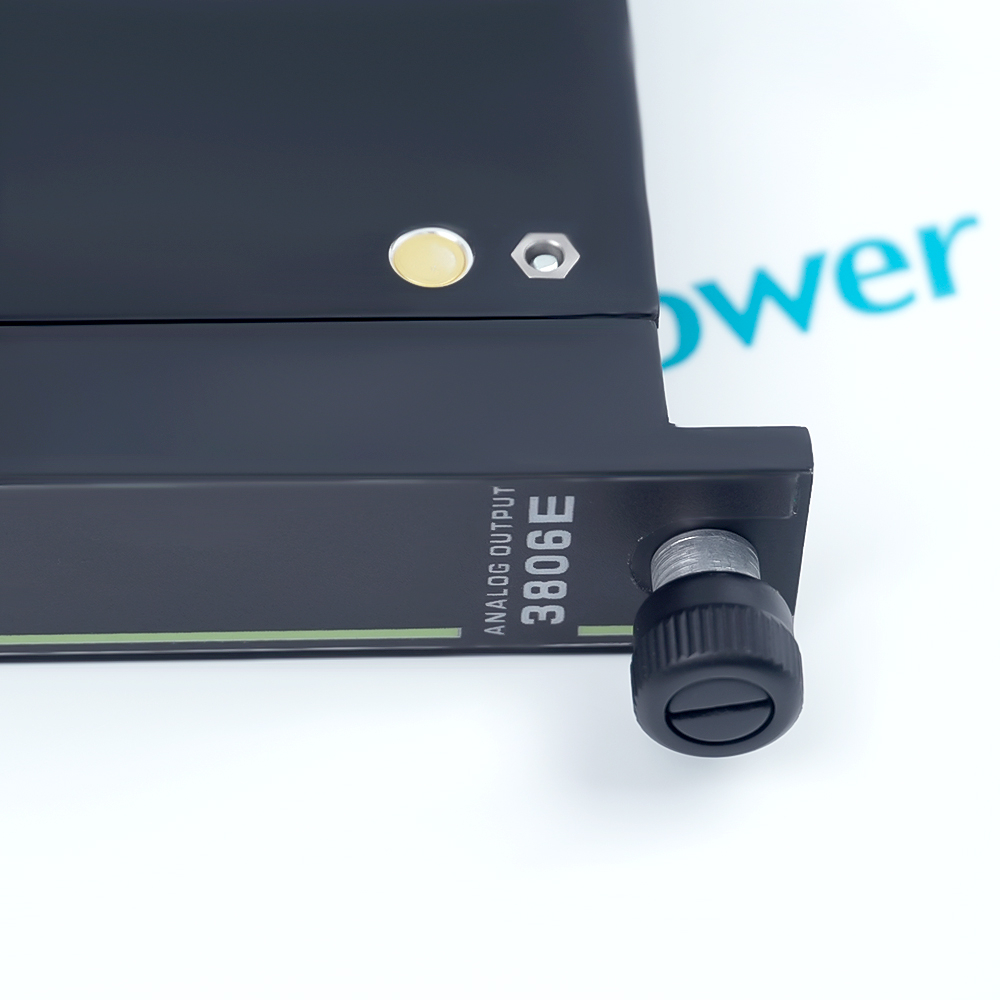
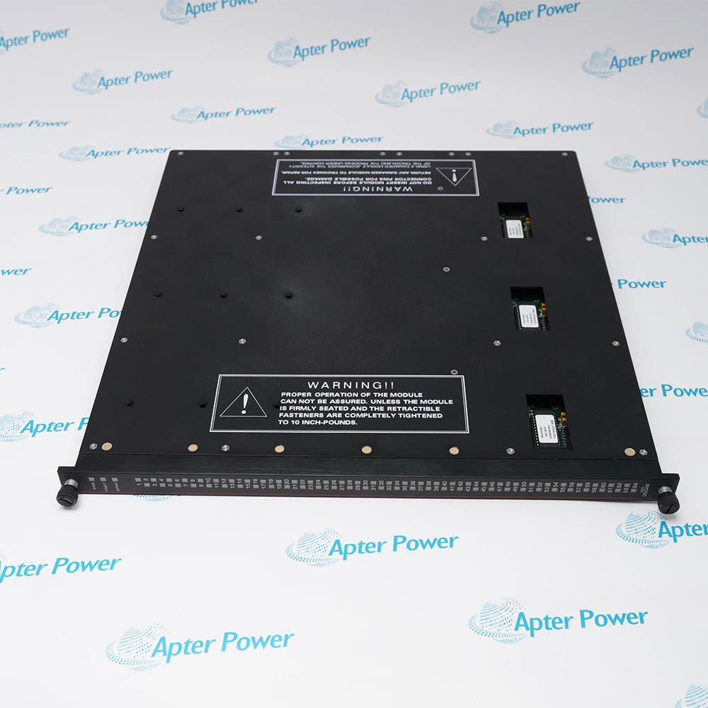
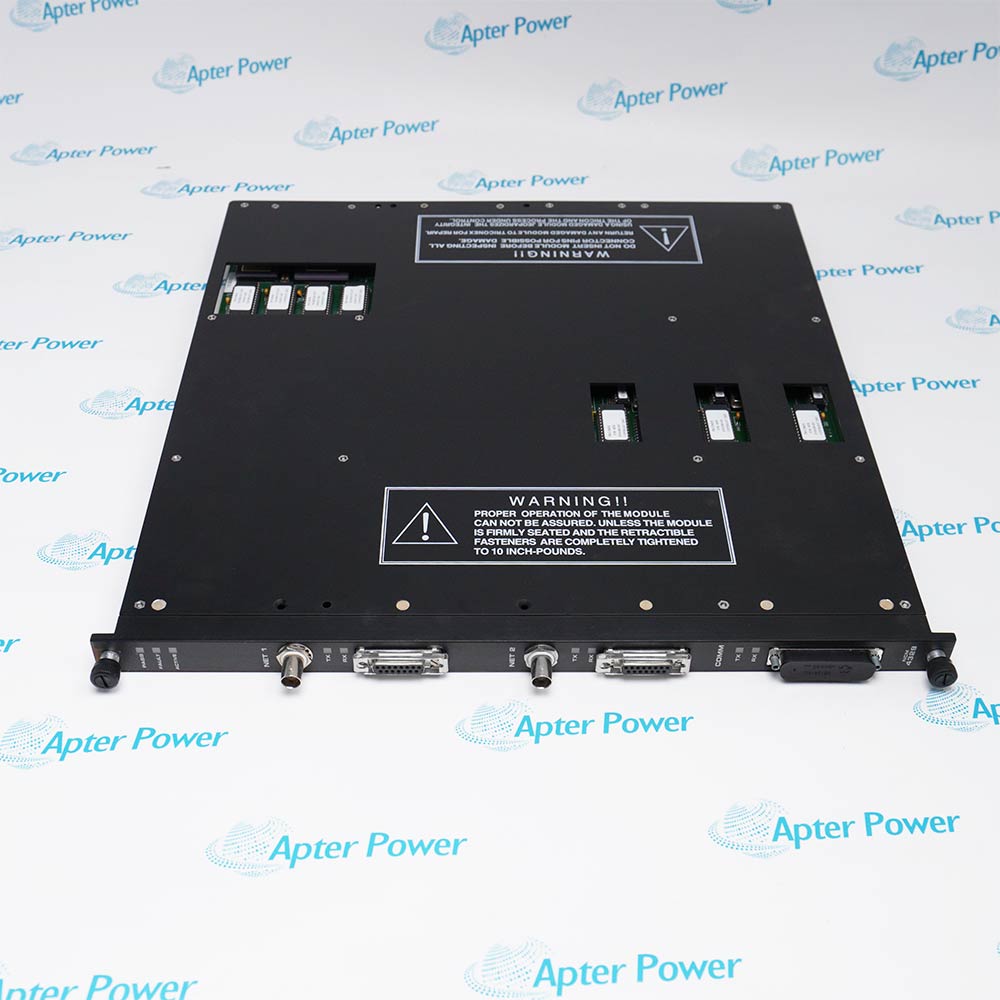
Include 3806E and every visible revision or assembly marking on the enquiry and quotation.
-
Check the offered item before ordering
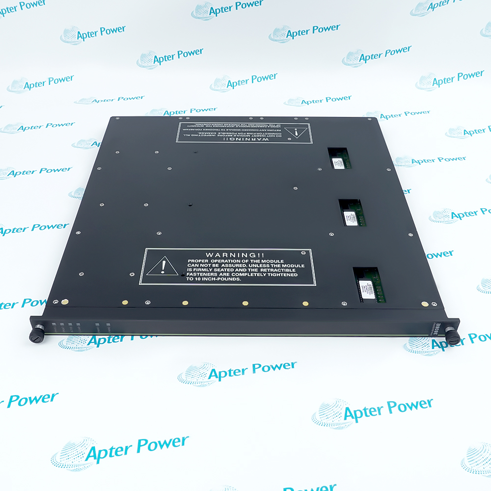
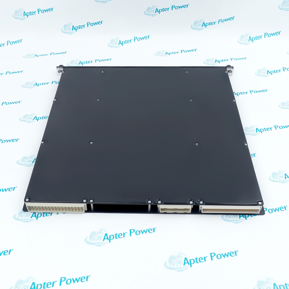
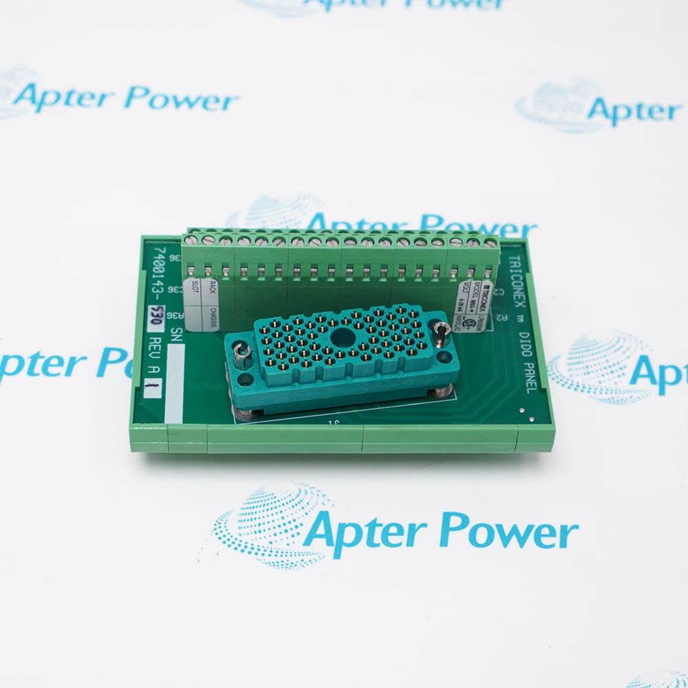
Request available label and connector photographs. Have maintenance compare the offered 3806E with the installed chassis, field termination and applicable Triconex documentation before ordering.
Technical specifications for 3806E
-
Manufacturer:Invensys
-
Product Category:DCS Systems
-
Spare Part Number:3806E
-
Weight:2.8 kg
-
Tariff Code:8537101190
-
System:Tricon v9-v10; verify installed chassis version
-
Module function:TMR analog output
-
Output count:8 total
-
Standard outputs:6 outputs, 4-20 mA
-
High-current outputs:2 outputs, 20-320 mA
-
Point mapping:Points 1 and 5 high-current; points 2-4 and 6-8 standard
-
Output coupling:DC-coupled with commoned return
-
Resolution:12 bits
-
Recommended loop supply:24-32 V DC, 3 A minimum
-
Extended loop supply:20-36 V DC, 3 A minimum
-
External loop power:24 V DC nominal; 42.5 V DC maximum
-
4-20 mA overrange:2-21.2 mA
-
20-320 mA overrange:20-339.2 mA
-
Output accuracy:Less than 0.25% of stated full-scale range, 0-60 C
-
Standard-loop max load at 24 V:475 ohms
-
High-current max load at 24 V:25 ohms
-
Standard-loop max load at 32 V:825 ohms
-
High-current max load at 32 V:50 ohms
-
Logic power:Less than 15 W
-
Fault switch time:10 ms typical; 20 ms maximum
-
Front indicators:PASS, FAULT, ACTIVE, LOAD, PWR1, PWR2
-
Stripe code:Light green
-
Field interface:Separate termination assembly and cable to chassis backplane
-
Hot spare:Analog output family supports online replacement per Tricon guide; follow approved safety procedure
-
Shipping package:2.1cm x 40.8cm x 39.8cm; 2.8kg
Information
- Triconex 3806E is a TMR analog output module with six 4-20 mA points and two 20-320 mA high-current points for applicable Tricon v9-v10 systems.
Point classes: Six standard; two high-current
Resolution: 12 bits
External loop power is wired at the termination assembly. The recommended supply is 24-32 V DC at 3 A minimum, with an extended 20-36 V DC operating range. Maximum field load depends on loop voltage and output class; at 24 V the guide lists 475 ohms for standard points and 25 ohms for high-current points.
The TMR output architecture uses voted triplicated channel data and current loopback diagnostics. PASS, FAULT, ACTIVE, LOAD, PWR1 and PWR2 indicators help isolate faults, but a lit power LED confirms voltage presence rather than adequate current capability. Assess the temperature and total-current derating table under real demand.
-
Triconex 3806E original technical reference
Original planning guide excerpt, 7 pages. Architecture, front panel, exact model table, load limits and derating. -
3806E engineering technical data
TMR output ratings, channel behavior, field isolation, diagnostics and service boundaries. Apter Power PDF, 1 page.
Application boundary: Confirm the safety application, mixed output ranges, termination assembly, field supply and site proof-test plan.
-
Standard current loops
Use six 4-20 mA points for suitable field devices after checking load and supply voltage at the termination. -
High-current actuators
Assign points 1 and 5 to documented 20-320 mA loads. Assess thermal derating and supply current at maximum demand. -
Redundant loop supply
The termination can accept redundant field loop power sources. Interpret PWR1/PWR2 as voltage-presence indications only. -
Safety maintenance
Use the configured hot-spare feature and approved replacement/proof-test procedure to preserve the safety function.
Follow the plant bypass, change-control and proof-test procedure before work on the TMR output module.
Do not wire a high-current load to a standard output or swap points 1 and 5 with the six 4-20 mA points.
Match the separate termination assembly, cable, connector and configured chassis slot before installation.
Measure voltage and current at the termination under the worst combined demand; PWR LEDs show presence only.
Evaluate total output current and ambient temperature against the original guide table for the installed loop voltage.
Capture PASS/FAULT/ACTIVE/LOAD indications, controller events and loopback measurements before removing the module.
Alternative Names
Technical notes
Output mapping: Points 1 and 5 are 20-320 mA; points 2-4 and 6-8 are 4-20 mA. Match the actual Tricon configuration and field termination.
Loop power: External field power is required. Verify voltage and current under the combined output load; PWR LEDs indicate presence rather than adequate capacity.
Technical source: Triconex Planning and Installation Guide for Tricon v9-v10 Systems, Assembly 9700077-012.

FAQ View All FAQ
-
How should the 4-20 mA and 20-320 mA channels of Triconex 3806E be mapped during migration?Trace each of eight configured output points to the physical termination. Points 1 and 5 are high-current; confirm field-device loads, controller project and termination drawing before transfer.
-
Why can the LOAD indication on Triconex 3806E appear while loop power LEDs are lit?PWR1/PWR2 detect the presence of loop voltage, not sufficient current capability for every connected load. Check commanded current, load wiring and supply under actual demand.
-
What should be investigated when one Triconex 3806E output does not reach its commanded current?Measure loop voltage at the termination assembly, wiring resistance and load impedance; compare the selected output class and supply-dependent load limit.
-
How is a channel diagnostic fault on Triconex 3806E distinguished from whole-module failure?Review the FAULT indication, controller diagnostics and both loopback circuits for the affected point. The source notes a channel fault can light FAULT without establishing total module failure.
-
What must be verified before using the hot-spare behavior of Triconex 3806E?Confirm the installed chassis configuration, spare slot, termination compatibility and approved maintenance procedure; plan a controlled proof test for the safety function.
-
How should loop supply sizing for Triconex 3806E be checked at maximum demand?Sum the required current for all commanded outputs, consider the guide temperature-derating table and measure voltage at the termination during the worst operating case.
-
What does the light-green stripe on Triconex 3806E help verify?It supports front-panel identity against the Tricon planning guide, but the full model label, point configuration and termination assembly must still be matched.
-
Which evidence should accompany a replacement enquiry for Triconex 3806E?Send module marking, chassis and termination identifiers, loop-power drawing, point map, diagnostic log and maintenance/proof-test procedure for review.
Supporting new and legacy automation
-
Please try to be as accurate as possible with your search.
-
We can quote you on 1000s of specialist parts, even if they are not listed on our website.
-
We can't find any results for “”.
Related cases and sourcing guidance
View all case studiesYou May Also Like
Product Browsing History
-
Whatsapp: +86 18030235313
Send us a message. -
sales13@apterpower.com
Complete our online form. -
+86 18030235313
Speak to our team in your native language.