Speak to a sourcing specialist
sales13@apterpower.com
Get a quick price for FCM10E P0914YM
E-mail *
Mobile *
Company
Content *
Quantity *
Upload (gif, jpg, jpeg, png, bmp, doc, docx, xls, xlsx, ppt, pdf, csv)
For more information on how your data is processed and stored by Apterpower please read our privacy policy

What happens after you enquire

  • 1

    Requirement review

    We review the part number, quantity and delivery requirements and ask for any missing details.
  • 2

    Quotation and availability

    We confirm the proposed item, condition, availability, price and estimated lead time in the quotation.
  • 3

    Order confirmation and dispatch

    Once the quotation and purchasing details are agreed, your contact will coordinate the order and available dispatch information.

Technical specifications for FCM10E P0914YM

  • Manufacturer:
    Invensys
  • Product Category:
    DCS Systems
  • Spare Part Number:
    FCM10E P0914YM
  • Estimated shipping dimensions:
    4.4x12.6x11.4cm
  • Weight:
    0.34 kg
  • Tariff Code:
    8537101190
  • Counliy of origin:
    USA
  • Ethernet trunk rate:
    10 Mbps
  • Trunk physical interface:
    10BASE2 coaxial Ethernet
  • Module Fieldbus rate:
    2 Mbps
  • Maximum FBMs per interface or pair:
    30
  • Maximum FCM10E pairs per trunk:
    30
  • Redundant configuration:
    2 FCM10E modules per grouping
  • Nonredundant configuration:
    1 FCM10E module per grouping
  • Front indicators:
    6 LEDs
  • Supply voltage:
    24 V DC; +5%, -10%
  • Maximum power consumption:
    7 W at 24 V DC
  • Maximum heat dissipation:
    7 W at 24 V DC
  • Vibration:
    0.75 g; 5–200 Hz
  • Operating temperature:
    -20 to +70 °C
  • Storage temperature:
    -40 to +70 °C
  • Relative humidity:
    5–95%, noncondensing
  • Operating altitude:
    -300 to +3000 m
  • Storage altitude:
    -300 to +12000 m
  • Contamination classification:
    ISA S71.04 Class G3
  • Pollution degree:
    2; IEC 664-1
  • Baseplate mounting:
    DIN rail or rack

Information

Overview Manuals Common Applications Product Precautions
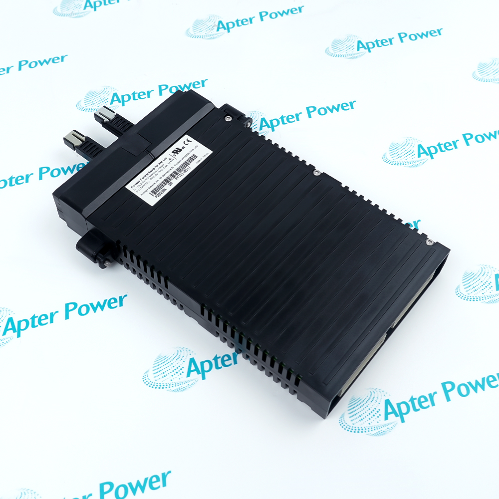
Foxboro FCM10E P0914YM can be installed as a single communications interface or as a redundant pair, keeping the FBM grouping connected to its control-station network.
  • Provides galvanic separation between the trunk and module communication circuits.
  • Fits a shared modular baseplate with FBM equipment.
  • Indicates operating status and traffic direction through six front-panel LEDs.
  • Supports removal without disconnecting power or communication cabling.

The Ethernet trunk may include additional equipment groupings and an optional fiber-optic extension through suitable conversion equipment. The local module Fieldbus remains a separate segment serving the associated FBMs.

Important Notice: Check the actual trunk topology, group membership and redundancy arrangement before isolating a communication path.

Foxboro FCM10E P0914YM Manuals & Downloads
Foxboro FCM10E P0914YM Manufacturer Technical Reference — Selected Pages (PDF)Foxboro FCM10E P0914YM Installation & Commissioning Guide (PDF)

The technical reference covers network architecture and electrical ratings. The commissioning guide addresses trunk identification, redundant-path checks and communication fault isolation.


DIN-rail I/O communication
Connect local FBM groups to an I/A Series control-station trunk.
Redundant communications grouping
Fit paired interfaces where the installed topology requires two communication modules.
Multiple equipment groups
Serve separate FBM groups along a common Ethernet trunk within the supported node limits.
Extended trunk segments
Use suitable media converters when a planned trunk extension crosses a fiber-optic segment.
Plan communication isolation and restoration before servicing Foxboro FCM10E P0914YM.
1
Identify the 10BASE2 trunk separately from the local 2 Mbps module Fieldbus.
2
Preserve A/B path identification when working on redundant connections.
3
Keep the associated grouping within the thirty-FBM limit.
4
Account for all FCM pairs attached to the same Ethernet trunk.
5
Verify both modules are installed when redundancy is required.
6
Budget supply capacity and enclosure heat for each installed interface.
7
Use separate media-conversion equipment for any fiber-optic trunk extension.
8
Confirm controller communication and affected FBM status after reconnecting a path.

Technical notes

A baseplate position count and a communication-group limit are separate constraints. Up to eight modules fit the described baseplate arrangement, while an FCM10E interface or redundant pair supports up to thirty FBMs across its grouping.

FAQ View All FAQ

  • How does FCM10E P0914YM connect a 10 Mbps trunk to 2 Mbps FBMs?
    It translates the control-station Ethernet signals into the module-Fieldbus signals and performs the reverse conversion for traffic returning from the FBMs.
  • Does using two FCM10E P0914YM modules double the FBM grouping capacity?
    No. A single interface or a redundant pair supports up to 30 FBMs. The second module provides redundancy rather than a second 30-FBM allocation for the same grouping.
  • How many FCM10E P0914YM pairs can share the Ethernet trunk Fieldbus?
    Up to 30 FCM10E pairs can connect to the trunk. This trunk-level limit is separate from the maximum number of FBMs within each grouping.
  • Which circuits are galvanically separated by FCM10E P0914YM?
    The module isolates the 10 Mbps Ethernet trunk Fieldbus from the 2 Mbps module Fieldbus. The isolation boundary is between these two communication domains.
  • What do the different LED colors on FCM10E P0914YM show?
    Red and green LEDs indicate the module operating status. Amber LEDs show data traffic and its direction between the control-station side and the associated FBMs.
  • What supply and heat allowances follow from a redundant FCM10E P0914YM pair?
    Each module requires up to 7 W at 24 V DC and dissipates up to 7 W. Two modules therefore require a calculated allowance of up to 14 W for the pair, before other equipment is added.
  • Can FCM10E P0914YM itself be treated as a direct fiber-optic trunk interface?
    No. Its trunk interface is 10BASE2 coaxial Ethernet. An optional fiber extension uses separate 10BASE2-to-fiber and fiber-to-10BASE2 conversion equipment.
  • Why can the FBM limit of FCM10E P0914YM exceed the slot count of one baseplate?
    The communication grouping may include multiple connected baseplates. The described baseplate supports up to eight FBMs or a mix of FBMs and FCMs, while the interface grouping supports up to 30 FBMs in total.
Related reading

Related cases and sourcing guidance

View all case studies
SPEAK TO OUR TEAM
Let’s find the right solution for you.
Send us the part number, quantity and delivery destination. Our team will help confirm availability and lead time.
  • Whatsapp: +86 18030235313

    Send us a message.
  • sales13@apterpower.com

    Complete our online form.
  • +86 18030235313

    Speak to our team in your native language.