











Get Parts Quote
Name
Company *
Phone *
Email *
Address
City
State / Province / Region
Zipcode
Country
Quantity *
Part Number *
Manufacturer
Preferred Condition
Additional Information
Cancel
ICS Triplex T3419
ICS Triplex T3419
ICS Triplex T3419
ICS Triplex T3419
ICS Triplex T3419
ICS Triplex T3419
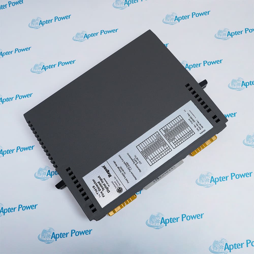
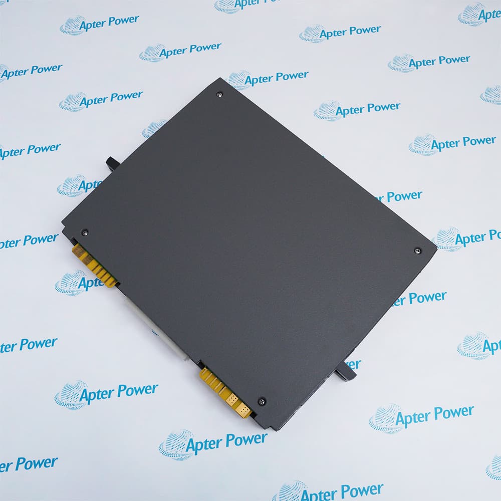
Product image is representative; revision or series may vary. Contact us to request a specific version.

T3419

Regent Fire Detector Input Module
In Stock
Ships by Tuesday, September 22
Fast Shipping Available

Product Describe:

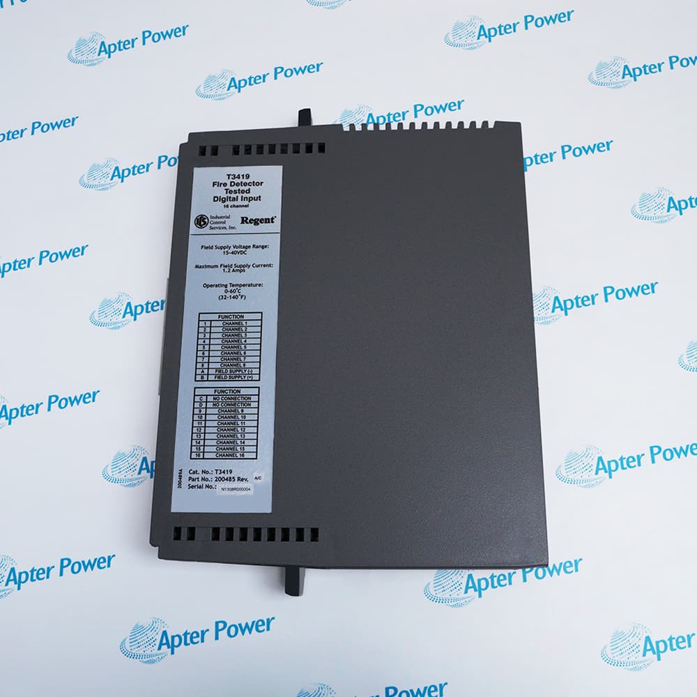
ICS Triplex T3419 is a Regent fire detector input module with 16 monitored and tested loops. It supplies regulated detector-loop voltage and reports alarm and wiring conditions to the safety application.

Ask our team:

Get a quick price for: T3419
Quantity*
Upload (gif, jpg, jpeg, png, bmp, doc, docx, xls, xlsx, ppt, pdf, csv)
For more information on how your data is processed and stored by Apterpower please read our privacy policy.

Technical specifications for T3419

Technical specifications for T3419

  • Manufacturer:
    ICS Triplex
  • Product Category:
    PLC Systems
  • Spare Part Number:
    T3419
  • Estimated shipping dimensions:
    3.2x26.5x36cm
  • Weight:
    1.52 kg
  • Tariff Code:
    8537101190
  • Counliy of origin:
    USA
  • Safetybus power:
    0.85 load units
  • Inputs:
    16
  • Field circuit:
    20 V detector loop, monitored and tested
  • Field-power voltage:
    15 to 40 Vdc
  • Field-power current:
    1.2 A maximum
  • Regulated loop voltage:
    23.5 Vdc
  • End-of-line resistor:
    3.0 kohm typical
  • Quiescent current:
    3 to 10 mA typical
  • Reset voltage:
    Less than 1 V
  • Reset current:
    Less than 20 mA
  • Test interval:
    15 s typical
  • Isolation:
    2500 V minimum
  • Operating temperature:
    0 to 60 deg C
  • Storage temperature:
    -40 to 85 deg C

Information

Information

Overview Manuals Common Applications Product Precautions
T3419 interfaces sixteen fire detector circuits to the Regent safety system and automatically tests their monitored wiring. Its regulated loop supply, end-of-line values and reset behavior must match the installed detector design.
  • Supervises sixteen fire detector input loops
  • Performs automatic loop testing and line monitoring
  • Provides regulated power for the connected detector circuits
  • Supports redundant detector arrangements for critical inputs

Each detector loop returns through the chassis terminal blocks to the field supply return, with external barriers where intrinsic safety is required. Commissioning includes loop-current checks, alarm simulation, wiring-fault tests, reset timing and verification of application annunciation.

Important Notice: Confirm T3419 identity, Regent chassis slot, detector types, terminal map, 15 to 40 Vdc field supply, 3.0 kohm end-of-line components, barriers, grounding, reset timing, application alarm mapping and complete loop proof test before commissioning.

Apter Power T3419 Manuals and Guides

The first document is the model-specific technical and system reference. The second is a distinct field workbook for installation, wiring, commissioning and acceptance records.


Plant fire-zone detection
Interfaces monitored detector circuits to the Regent safety application.
Combustible-area alarm loops
Supervises detector alarm and wiring conditions in engineered fire-protection zones.
Redundant detector voting
Supports paired sensor and module arrangements used to maintain detection during a controlled fault.
Intrinsic-safety detector circuits
Works with an approved external barrier when the installation requires intrinsically safe field wiring.
Read the applicable ICS Triplex installation instructions before work. Verify T3419, the installed host system and all configured field interfaces before isolation, wiring or commissioning.
1
Confirm T3419 and the assigned sixteen detector-loop identities.
2
Disable affected fire functions only under the approved impairment procedure.
3
Isolate field power and record every terminal and end-of-line component.
4
Verify detector compatibility with the regulated loop and current behavior.
5
Use the approved external barrier where intrinsic safety is required.
6
Check open and short protection before reconnecting field circuits.
7
Simulate alarm, wiring fault and programmable reset on every affected loop.
8
Restore fire-system annunciation and document the completed functional test.

Technical notes

Technical notes

Install T3419 in the documented Regent I/O chassis slot and connect detector loops through the associated terminal blocks with the correct end-of-line components. After replacement, test alarm, open-circuit, short-circuit and programmable reset behavior for all affected loops.

FAQS

  • What is the exact system role of T3419?
    It is the 16-loop Regent input module for monitored, automatically tested fire detector circuits.
  • Which host, rack or carrier is required for T3419?
    Use the engineered Regent I/O chassis slot and the terminal blocks assigned to that detector group.
  • What wiring or connector checks apply to T3419?
    Confirm detector polarity, field return, end-of-line component, shield and any external intrinsic-safety barrier.
  • How is T3419 configured for service?
    Map each detector alarm, line fault and reset control to the approved Regent application and preserve the programmed reset time.
  • Which diagnostics should be reviewed for T3419?
    Review alarm state, open and short circuit conditions, automatic test results, reset operation and module health.
  • What must be preserved when replacing T3419?
    Preserve fire-zone mapping, detector type, end-of-line value, barrier data, terminal wiring and impairment records.
  • How should T3419 be commissioned after installation?
    Restore field power, simulate alarm and wiring faults, exercise reset and verify all control-room annunciation.
  • What model-specific limitation must be checked for T3419?
    Do not treat T3419 as a generic 24 V digital input; its detector-loop regulation and supervision are model-specific.
Trusted by 5,000+ plants worldwide | Backed by our vast inventory of top-tier control parts, modules and cards, fast shipments are dispatched to cover your urgent needs. ABOUT US >>
Disclaimer: We are not an authorized distributor or distributor of the product manufacturer of this website, The product may have older date codes or be an older series than that available direct from the factory or authorized dealers. Because our company is not an authorized distributor of this product, the Original Manufacturer`s warranty does not apply.While many DCS PLC products will have firmware already installed, Our company makes no representation as to whether a DSC PLC product will or will not have firmware and, if it does have firmware, whether the firmware is the revision level that you need for your application. Our company also makes no representations as to your ability or right to download or otherwise obtain firmware for the product from our company, its distributors, or any other source. Our company also makes no representations as to your right to install any such firmware on the product. Our company will not obtain or supply firmware on your behalf. It is your obligation to comply with the terms of any End-User License Agreement or similar document related to obtaining or installing firmware.

Product Browsing History

We’re Here When You Need Us

From product insights to customer service needs, our experienced service team will focus on getting you what you need quickly

Enquire

Complete our online form.

Call Us

Speak to one of our team.

Live Chat

Send us a message.
