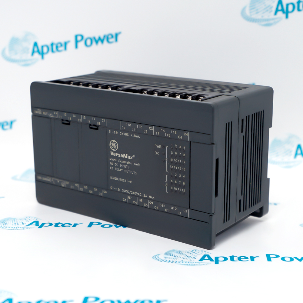
Technical specifications for IC670ALG621
-
Manufacturer:General Electric
-
Product Category:PLC Systems
-
Spare Part Number:IC670ALG621
-
Estimated shipping dimensions:5.3x8.5x8.1cm
-
Weight:0.25 kg
-
Tariff Code:8537101190
-
Counliy of origin:USA
-
Product family:Field Control
-
Signal category:RTD temperature/resistance input
-
Mounting:Field Control I/O terminal block
-
Station interface:Compatible Field Control BIU or processor
-
Configuration method:Station configuration using the supported programmer or host
-
Data role:Analog input with diagnostic status
-
Installation system:DIN-rail Field Control station
Information
- Uses the exact IC670ALG621 catalog identity
- Occupies a Field Control analog-input position
- Processes RTD resistance as temperature data
- Exchanges configured input and diagnostic information with the station interface
IC670ALG621 operates with Field Control I/O terminal block, Compatible station BIU or processor, Installed RTD field circuits, Approved channel configuration record.
Engineered applications include RTD temperature acquisition field station, Remote I/O cabinet integration, Installed-base module renewal, Controlled commissioning and diagnostics.
Important Notice: Verify the exact IC670ALG621 hardware marking, installed RTD type, conductor arrangement, terminal assignment and existing channel configuration before replacement.
Apter Power IC670ALG621 Manuals and Guides
Apter Power IC670ALG621 Technical Data and System Reference PDFIC670ALG621 Field Installation and Commissioning Workbook PDFThe first document presents model-specific technical data and system identity. The second provides a separate installation, wiring and commissioning workflow.
RTD temperature acquisition field station
Performs the documented rtd temperature acquisition function at a distributed Field Control station.
Remote I/O cabinet integration
Exchanges configured process data with the host through the installed bus interface.
Installed-base module renewal
Restores an exact catalog-number position while preserving terminal and data identity.
Controlled commissioning and diagnostics
Supports staged wiring, configuration, diagnostic and functional verification.
Verify the complete IC670ALG621 catalog marking and assigned Field Control position before work.
Place the connected RTD temperature acquisition process in its approved maintenance state before disturbing the station.
Isolate BIU and field power, then confirm a safe condition at the IC670ALG621 terminal block.
Label and record channel conductors, returns, shields and external supply wiring before disconnecting any conductor from IC670ALG621.
Use ESD controls and protect the module connector, terminal block keying and exposed electronics.
Restore only the documented channel range, scaling, alarms and default behavior; do not copy settings from an adjacent module.
Energize in a controlled sequence and review PWR, channel, module and network diagnostics.
Complete low, midpoint and high signal checks plus alarm and diagnostic verification and retain the final result before returning the process to service.

Technical notes
FAQ View All FAQ
-
What Field Control function is assigned to IC670ALG621?IC670ALG621 is ge fanuc field control rtd analog input module. It interfaces resistance-temperature sensing circuits with the installed Field Control station for host temperature acquisition and diagnostics.
-
Which station hardware must be paired with IC670ALG621?Use IC670ALG621 with the documented Field Control terminal block, compatible BIU or MFP, and the installed field control i/o terminal block.
-
Which IC670ALG621 identity should be checked before installation?Confirm the full IC670ALG621 catalog marking and the catalog number value IC670ALG621 against the installed station record.
-
How should field wiring be transferred when replacing IC670ALG621?Label and record channel conductors, returns, shields and external supply wiring before disconnecting any conductor from IC670ALG621.
-
Which configuration item is critical when commissioning IC670ALG621?Restore only the documented channel range, scaling, alarms and default behavior; do not copy settings from an adjacent module.
-
What diagnostic checks apply to IC670ALG621?Energize in a controlled sequence and review PWR, channel, module and network diagnostics.
-
How should the IC670ALG621 signal path be functionally tested?Complete low, midpoint and high signal checks plus alarm and diagnostic verification and retain the final result before returning the process to service.

-
Can IC670ALG621 be replaced by a visually similar Field Control module?No direct substitution should be assumed. Match IC670ALG621, its terminal assignment, data allocation, signal type, power arrangement, and the documented installation system value DIN-rail Field Control station before migration.
Supporting new and legacy automation
-
Please try to be as accurate as possible with your search.
-
We can quote you on 1000s of specialist parts, even if they are not listed on our website.
-
We can't find any results for “”.
Related cases and sourcing guidance
View all case studiesYou May Also Like
Product Browsing History
-
Whatsapp: +86 18030235313
Send us a message. -
sales13@apterpower.com
Complete our online form. -
+86 18030235313
Speak to our team in your native language.