-
Match the complete marking
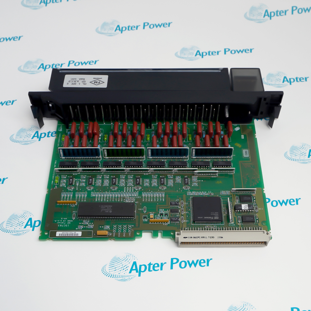
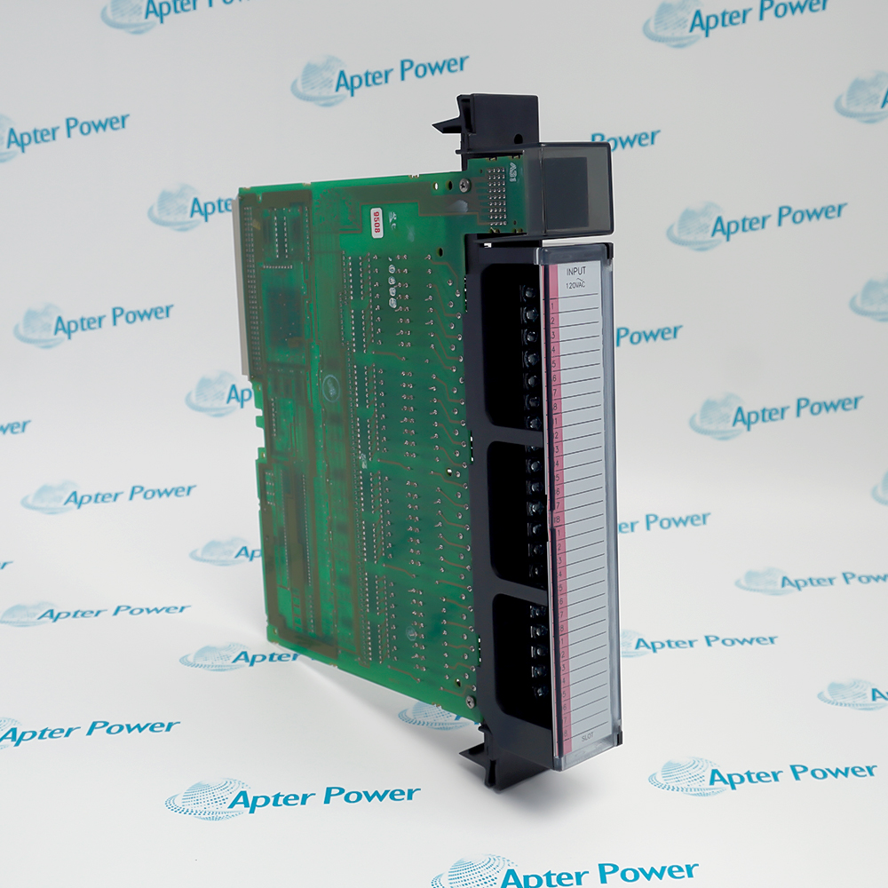
Include the complete IC697MDL250 marking and all series or revision details shown on the item. Match the offered hardware with the installed configuration before accepting the quotation.
-
Check the offered item before ordering
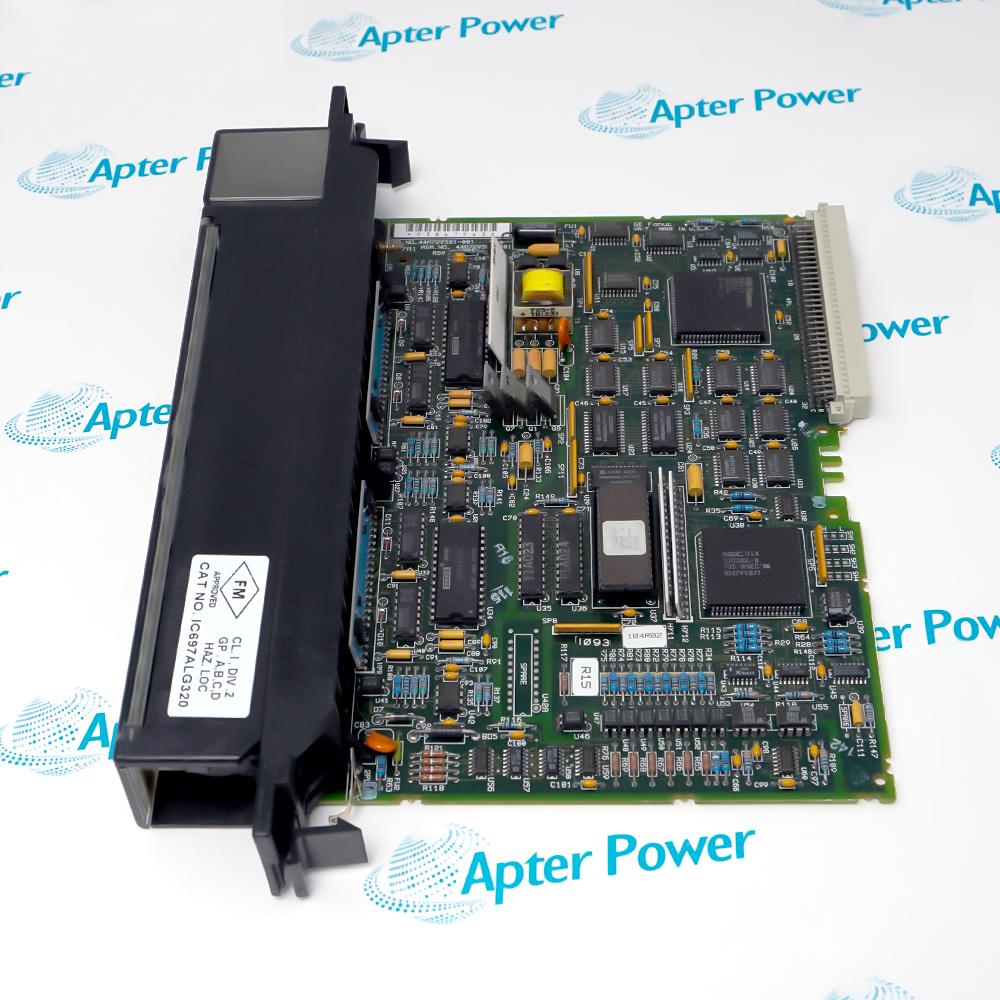
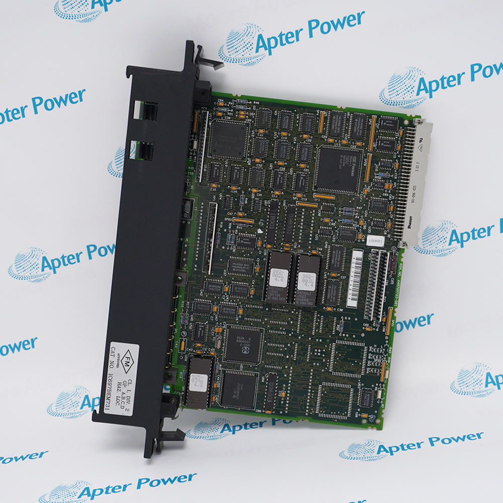
Request available label and connector photos. Have your maintenance team compare the offered IC697MDL250 with the installed equipment and applicable GE documentation.
Technical specifications for IC697MDL250
-
Manufacturer:General Electric
-
Product Category:PLC Systems
-
Spare Part Number:IC697MDL250
-
Weight:0.62 kg
-
Tariff Code:8537101190
-
Rated input:120 VAC sinusoidal
-
Frequency range:47 to 63 Hz
-
Input count:32, four groups of eight
-
On-state voltage:75 to 132 VAC
-
Off-state voltage:0 to 25 VAC
-
On-state current:6 to 15 mA
-
Typical input current:10 mA at rated voltage
-
Typical filter delay:20 ms
-
Input-to-backplane isolation:1500 V RMS
-
Group-to-group isolation:500 V RMS
-
5 V bus current:0.35 A
-
Terminal conductors:22 to 14 AWG
Information
- GE IC697MDL250 allows separate AC input groups to share one rack slot, with per-point PLC-side indication and input characteristics suitable for evaluated contact and proximity-switch circuits.
Signal levels: 75–132 VAC on; 0–25 VAC off, at 47–63 Hz
Input processing: 20 ms typical filter; 10 mA typical at rated voltage
The reactive input circuit is designed for 120 VAC sinusoidal signals at 47 to 63 Hz. Compatibility with a two-wire proximity switch depends on both its on-state load-line relationship and off-state leakage below 2.2 mA. A switch that conducts enough current when on may still fail to produce a valid off state if leakage is excessive.
Point indicators show the logic-side input state, while software configuration assigns the I/O references without module DIP switches or jumpers. Mechanical keying helps preserve the correct module type in its rack slot. The detachable terminal board retains the field wiring during a module exchange and must remain associated with the correct slot.
IC697MDL250 Official Technical Reference Excerpt
GE Fanuc 120 VAC Input Module, GFK-0084J, in GFK-0600F provides the manufacturer reference for IC697MDL250 and its applicable system arrangement. PDF · 6 pages.IC697MDL250 Installation & Verification Guide
Apter Power guide covering AC group identification, terminal-board wiring, leakage evaluation and point-by-point input testing. PDF · 5 pages.
Application scope: Applications below require suitable voltage, frequency, leakage and timing. They do not imply suitability as a dedicated safety or high-speed counting input.
Contact monitoring
Acquire pushbutton, selector and limit-switch states from evaluated 120 VAC circuits.Two-wire proximity sensing
Use switches whose on-state load line and off-state leakage satisfy the module input requirements.Grouped phase circuits
Keep four isolated eight-point groups assigned to their approved AC phases and returns.Rack input replacement
Retain the existing keyed position and terminal board while restoring the programmed input mapping.
Remove the relevant electrical energy before removing a module or terminal board.
Preserve each eight-point group supply and return; avoid unintended cross-connections.
Check the off-state leakage of electronic proximity switches.
Account for the typical 20 ms filter and the application scan.
Keep the wired board and its identification strap associated with the correct slot.
Prove on and off transitions at the field device, module LED and PLC reference.
Alternative Names
Technical notes
Input thresholds: Evaluate on and off voltages at the actual AC frequency and waveform.
Proximity compatibility: Both load-line operation and leakage determine suitability for an electronic switch.
Indication scope: Point LEDs indicate the PLC side of the input circuit; they are not a substitute for checking field wiring.

FAQ View All FAQ
-
Can the four IC697MDL250 input groups use different AC phases?Yes. Each group of eight inputs is isolated from the others. Maintain a separate power connection for each group and follow the intended phase and neutral arrangement.
-
What voltage makes an IC697MDL250 point reliably on?The specified on-state range is 75 to 132 VAC at 47 to 63 Hz with a sinusoidal waveform. The off-state range is 0 to 25 VAC; do not treat the intervening region as a guaranteed state.
-
Why might a two-wire proximity switch keep IC697MDL250 on after release?Excessive off-state leakage can prevent a valid off condition. The switch compatibility check requires off-state current below 2.2 mA as well as a suitable on-state operating point.
-
Does IC697MDL250 report a very short contact pulse without filtering?No. Its input filter delay is typically 20 ms. Assess the minimum pulse duration and PLC scan behavior before using it for short events.
-
Do IC697MDL250 point LEDs show field voltage directly?The LEDs indicate on/off status on the logic side of the input circuit. Compare them with both measured field conditions and the assigned PLC input references.
-
Which backplane load should be allowed for IC697MDL250?Allow 0.35 A from the 5 V backplane bus. This is distinct from the 120 VAC field input circuits and their reactive input current.
-
Are IC697MDL250 input references selected by jumpers?No. I/O references are assigned through the PLC configuration software. Preserve the software mapping when exchanging the module.
-
Can two wires share an IC697MDL250 terminal?The detachable terminal board accepts 22 to 14 AWG conductors. Two conductors may share a terminal only when they are the same size; retain correct grouping and secure the wire bundle.
Supporting new and legacy automation
-
Please try to be as accurate as possible with your search.
-
We can quote you on 1000s of specialist parts, even if they are not listed on our website.
-
We can't find any results for “”.
You May Also Like
Product Browsing History
-
Whatsapp: +86 18030235313
Send us a message. -
sales13@apterpower.com
Complete our online form. -
+86 18030235313
Speak to our team in your native language.