Speak to a sourcing specialist
sales13@apterpower.com

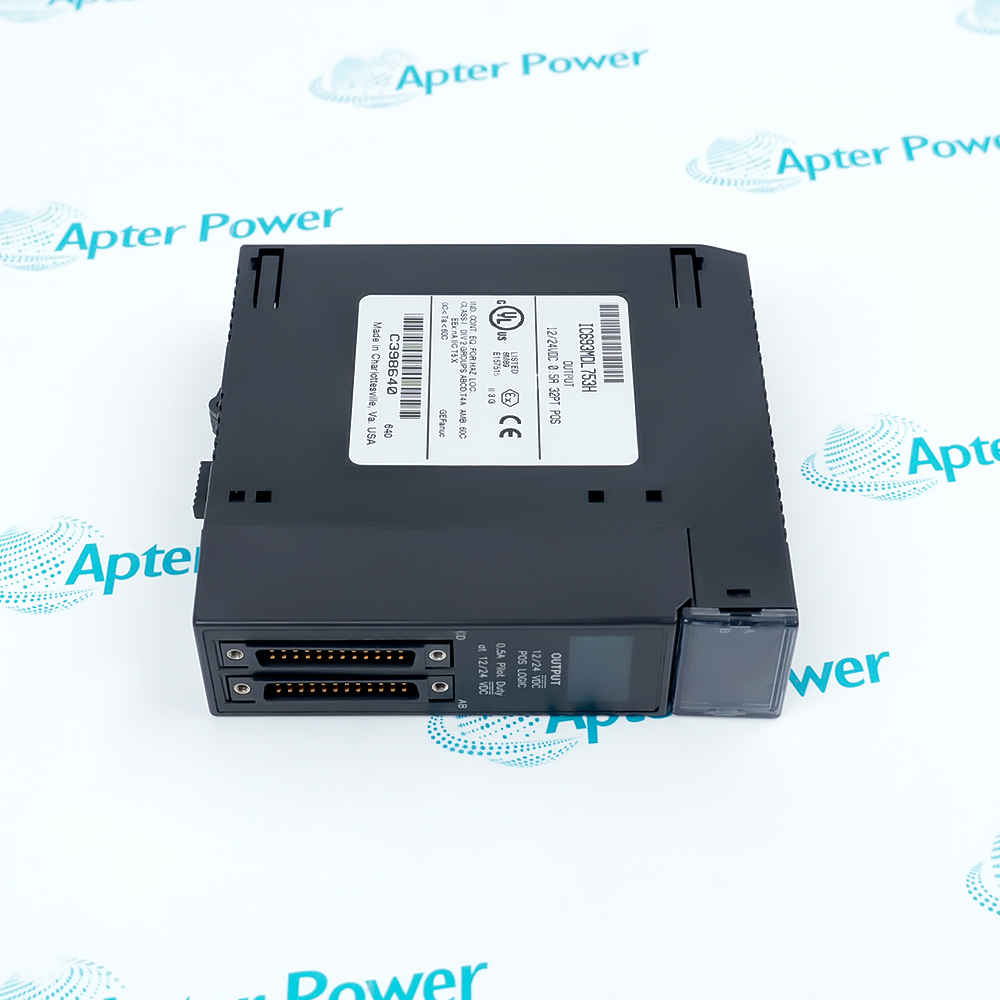
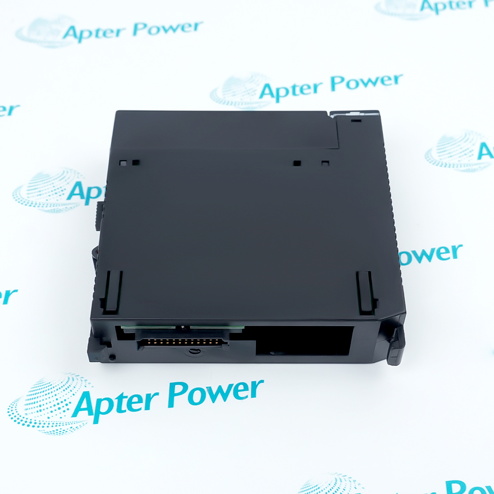
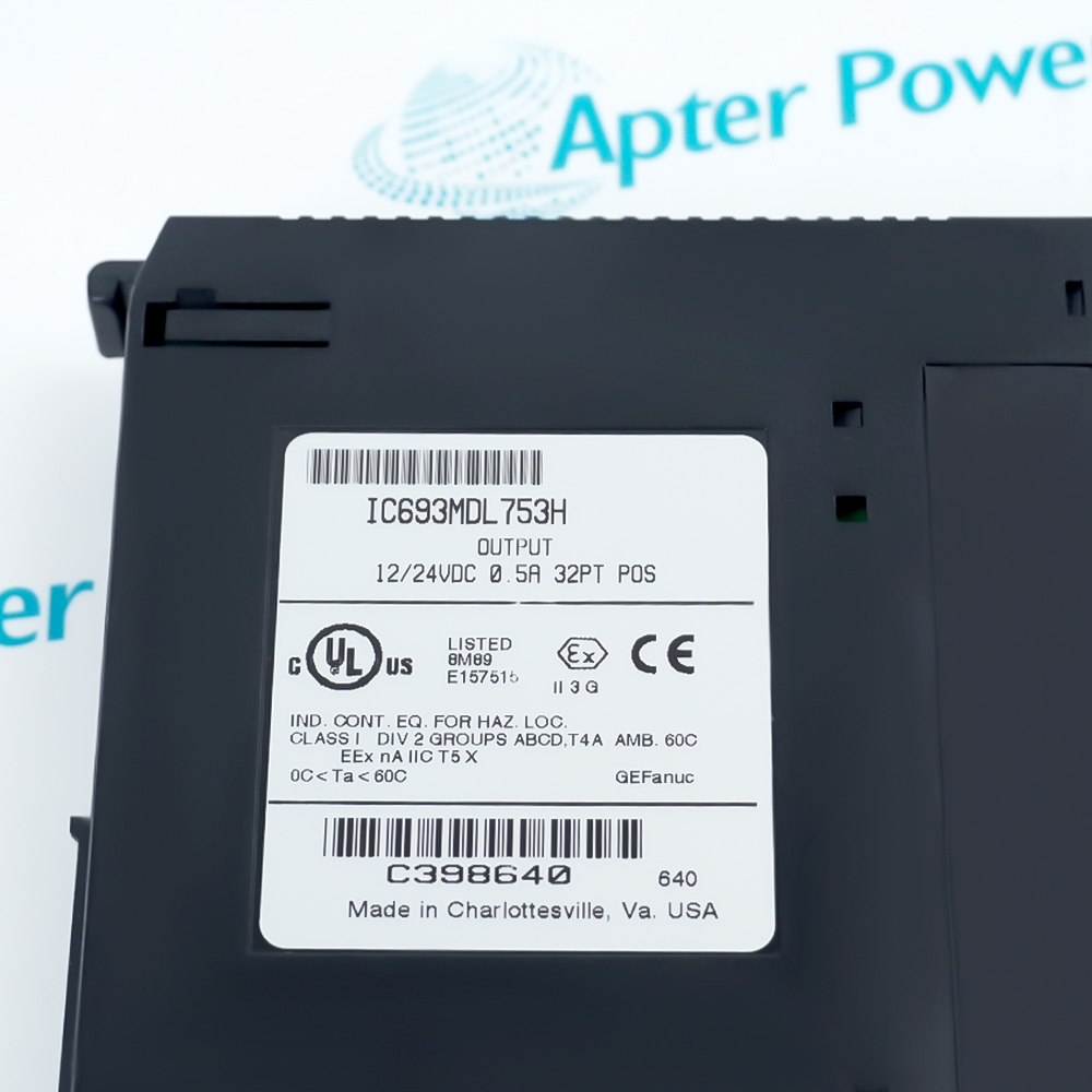
IC693MDL753

Discrete Output Module
In Stock
Ships by Friday, November 6
Fast Shipping Available
GE IC693MDL753 (1)
GE IC693MDL753 (2)
GE IC693MDL753 (3)
GE IC693MDL753 (1)
GE IC693MDL753 (2)
GE IC693MDL753 (3)
Product image is representative; revision or series may vary. Contact us to request a specific version.

Product Describe:

GE IC693MDL753 provides 32 sourcing outputs for Series 90-30 control stations. Four isolated eight-point groups switch 10.2–28.8 VDC loads from discrete %Q output data.
Get a quick price for IC693MDL753
E-mail *
Mobile *
Company
Content *
Quantity *
Upload (gif, jpg, jpeg, png, bmp, doc, docx, xls, xlsx, ppt, pdf, csv)
For more information on how your data is processed and stored by Apterpower please read our privacy policy

What happens after you enquire

  • 1

    Requirement review

    We review the part number, quantity and delivery requirements and ask for any missing details.
  • 2

    Quotation and availability

    We confirm the proposed item, condition, availability, price and estimated lead time in the quotation.
  • 3

    Order confirmation and dispatch

    Once the quotation and purchasing details are agreed, your contact will coordinate the order and available dispatch information.

Technical specifications for IC693MDL753

  • Manufacturer:
    General Electric
  • Product Category:
    PLC Systems
  • Spare Part Number:
    IC693MDL753
  • Estimated shipping dimensions:
    3.6x13x13.5cm
  • Weight:
    0.28 kg
  • Tariff Code:
    8537101190
  • Counliy of origin:
    USA
  • Product type:
    Series 90-30 positive-logic discrete output module
  • Output points:
    32
  • Output grouping:
    4 isolated groups of 8
  • Rated voltage:
    12–24 VDC, positive logic
  • Output voltage range:
    10.2–28.8 VDC
  • Output current:
    0.5 A maximum per point
  • Group current limit:
    4 A maximum per group
  • Common-pin current limit:
    3 A maximum per common pin
  • Inrush current:
    5.4 A for 10 ms
  • On-state voltage drop:
    0.3 VDC
  • Off-state leakage:
    0.1 mA maximum
  • Response time:
    0.5 ms maximum ON; 0.5 ms maximum OFF
  • Isolation:
    1500 V field-to-logic; 250 V between groups
  • Backplane consumption:
    260 mA maximum from the 5 V bus

Information

Overview Manuals Common Applications Product Precautions
GE IC693MDL753 is a 12/24 VDC positive-logic output module with four isolated groups and two 24-pin field connectors for Series 90-30 baseplates.
  • 32 positive-logic sourcing outputs
  • Four isolated groups of eight points
  • Two front 24-pin field connectors
  • 32-bit discrete %Q output mapping

The module installs in an I/O slot of a 5-slot or 10-slot Series 90-30 baseplate. The right connector serves groups A and B, while the left connector serves groups C and D; user-supplied field power drives the connected loads.

Important Notice: Verify the exact IC693MDL753 label, positive-logic polarity, group supply/common wiring, current limits and the complete point-to-%Q assignment before commissioning.

GE IC693MDL753 Manuals & Downloads
GE IC693MDL753 Official Technical Reference Excerpt (PDF) GE IC693MDL753 Installation & Commissioning Guide (PDF)

Important Notice: The Technical Reference preserves the exact manufacturer specification and wiring pages; the Installation & Commissioning Guide organizes site preparation, connector control, electrical checks and point-by-point acceptance.


Four-zone actuator marshalling
Separate 12/24 VDC loads into A, B, C and D output groups while maintaining a dedicated common for each group.
Mixed 12 VDC and 24 VDC load groups
Use different isolated groups for different load voltages across the 10.2 to 28.8 VDC output range.
High-density Series 90-30 panel service
Restore a 32-point positive-logic output position while preserving the rack slot, %Q map and two connector assignments.
Command-to-field acceptance testing
Commission each point through the %Q command, matching LED, connector measurement and controlled field-device response.
Apply the following model-specific checks before replacing, energizing or commissioning GE IC693MDL753.
1
Verify the complete IC693MDL753 catalog number and installed Series 90-30 station before replacement.
2
Place commanded loads in a safe state and isolate user field power before disturbing either connector.
3
Keep positive-logic polarity and the 10.2 to 28.8 VDC output range.
4
Limit each output to 0.5 A and each isolated eight-point group to 4 A maximum.
5
Observe the 3 A limit for each common pin; use both group supply pins when group current is between 3 A and 4 A.
6
Preserve the right-front A/B and left-front C/D connector assignment during reconnection.
7
Confirm the complete 32-bit %Q mapping before energizing user field power and connected loads.
8
Test every point under controlled conditions; front LEDs show commanded status but do not replace a field-response check.

Technical notes

Install IC693MDL753 in the intended Series 90-30 I/O position. Preserve the right A/B and left C/D connector assignment, verify each group supply/common and current budget, then test all 32 %Q commands against the corresponding LED, terminal voltage and field response.

FAQ View All FAQ

  • How are the 32 outputs in GE IC693MDL753 organized?
    They are arranged as four isolated groups of eight points: A1–A8, B1–B8, C1–C8 and D1–D8, with a separate common for each group.
  • What field-voltage range should be verified for GE IC693MDL753?
    The rated value is 12–24 VDC positive logic, and the output-voltage range is 10.2–28.8 VDC.
  • What current limits apply to GE IC693MDL753?
    Use 0.5 A maximum per point, 4 A maximum per eight-point group and 3 A maximum per group common pin.
  • When must both supply pins be wired on GE IC693MDL753?
    Both group supply pins are required when total load current for that group is between 3 A and 4 A; using both pins is recommended generally.
  • What happens to GE IC693MDL753 outputs when the CPU stops?
    All 32 outputs are forced OFF when the CPU is stopped.
  • How is GE IC693MDL753 represented in the PLC output table?
    It is configured as a 32-point output type and occupies 32 bits of discrete %Q output data.
  • Which connector serves each output group on GE IC693MDL753?
    The right-front 24-pin connector serves groups A and B; the left-front 24-pin connector serves groups C and D.
  • What status and diagnostic information does GE IC693MDL753 provide?
    Front LEDs indicate the ON/OFF state of each point. The module does not report special fault or alarm diagnostics.
Related reading

Related cases and sourcing guidance

View all case studies