-
Match the complete marking
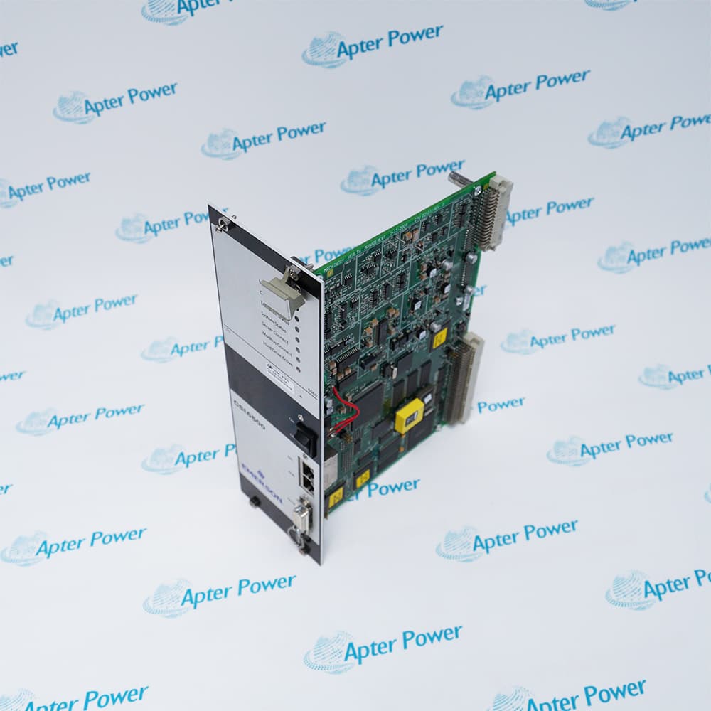
Match the complete Emerson A6220 marking and the installed configuration. Compare channel sensitivity, eccentricity range and backplane interfaces.
-
Check the offered item before ordering
Please request clear photographs of Emerson A6220, including its complete label and interfaces. Ask your maintenance team to compare the offered unit with the installed equipment and the applicable Emerson A6220 technical specifications before approving the order.
Technical specifications for A6220
-
Manufacturer:Emerson
-
Product Category:Machinery Monitoring Systems
-
Spare Part Number:A6220
-
Weight:0.3 kg
-
Tariff Code:8537101190
-
Input channels:2 independent differential inputs
-
Input resistance:>100 kΩ
-
Measurement modes:Peak-to-peak; min/max; continuous gap
-
Signal range:0–400 mV peak minimum; 0–8000 mV peak maximum
-
Sensor supply:Nominal -26.7 VDC
-
Sensor current:20 mA nominal; 35 mA maximum
-
Current output:0/4–20 mA per channel; load <500 Ω
-
Current-output accuracy:±1% of full scale
-
Voltage output:0–10 VDC per channel; load >10 kΩ
-
Output settling time:Configurable 0–10 s
-
Limit multiplier:1.00–4.99
-
Operating temperature:0 to +65 °C
Information
- Emerson A6220 follows the eccentricity collar near a machine thrust bearing during slow roll. Its two independent channels separate the displacement measurement from the alarm and output functions used by the machinery-protection system.
Measurement modes: Peak-to-peak, min/max and continuous gap
Proportional outputs: 0/4–20 mA and 0–10 V per channel
Measurement range, engineering units and sensor sensitivity are configurable. Peak-to-peak, minimum/maximum and continuous-gap measurements are available, with a 60-second settling period for hot configuration. Buffered sensor signals are available separately from the proportional current, voltage and gap outputs.
Each channel has independent OK indication and alert/danger indication. Alarm limits are adjustable from 5 to 100% of full scale with 1% resolution; normal alarm delay is 0–5 seconds. Power, sensor, cable, overload, internal temperature and watchdog supervision support fault identification, while remote limit multiplication and trip bypass require controlled configuration.
A6220 Technical Reference
Technical material for Emerson A6220 covers channel architecture, configurable measurement modes and alarm/output limits. PDF · 5 pages.A6220 Installation & Verification Guide
Apter Power installation and verification guide covering sensor-chain readiness, output loading, configuration settling and alarm tests. PDF · 5 pages.
Application scope: Eccentricity monitoring supports slow-roll assessment of large sleeve-bearing machines. Shaft-bow interpretation requires the intended collar geometry and low-speed operating condition.
Slow-roll shaft bow
Measure displacement at an eccentricity collar while the rotor turns below 600 rpm.Two independent channels
Monitor two displacement inputs with individual OK, alert and danger indication.Gap trending
Use continuous-gap measurement and the separate proportional gap output to observe shaft-position changes.Protection integration
Send characteristic values to the control system while checking the independently configured alarm and relay paths.
Match sensor position and target collar to the installed eccentricity measurement.
Use the correct probe/driver sensitivity and engineering-unit scaling.
Account for the 60-second hot-configuration settling time before judging the measured value.
Keep current-loop load below 500 Ω and voltage-output load above 10 kΩ.
Record the limit multiplier and trip-bypass state and restore them after testing.
Investigate sensor, cable or supply faults before accepting a normal-looking proportional output.
Alternative Names
Technical notes
Signal relationship: The sensor must view a suitable eccentricity collar for shaft-bow monitoring. A buffered raw-signal path is separate from the peak-to-peak or gap characteristic value used by proportional outputs and alarms.
Installation boundary: Test normal alarms, channel-not-OK response and the removal of any trip bypass independently. A proportional output agreeing with the display alone does not verify the shutdown path.
Technical basis: Emerson Protection Cards for AMS 6500 Classic Systems, A6220 specifications, November 2017. Values apply to the A6220 eccentricity-monitor design with a configured displacement measuring chain. Buffered bandwidth does not define the slow-roll eccentricity application range.

FAQ View All FAQ
-
Why is A6220 used during slow roll rather than only at rated speed?Eccentricity monitoring detects shaft bow using non-contact displacement at a collar below 600 rpm. This slow-roll condition separates the intended bow assessment from normal operating vibration.
-
Which measurements can A6220 derive from the displacement signal?It supports peak-to-peak, minimum/maximum and continuous-gap measurements. Measurement range, engineering units and sensor sensitivity are configurable.
-
Does the buffered output of A6220 represent the same quantity as its current output?No. The buffered output carries the raw transducer signal, while 0/4–20 mA is proportional to the configured main characteristic value. Use the correct signal for the test.
-
How long should A6220 be allowed to settle after hot configuration?The specified measurement-mode settling time is 60 seconds. Its proportional-output settling setting is a separate configurable 0–10 second value.
-
What current-loop burden is permitted on A6220?The load must be below 500 Ω for the 0/4–20 mA output. Accuracy is ±1% of full scale under the applicable operating conditions.
-
How finely can alert and danger thresholds be adjusted on A6220?The adjustment range is 5–100% of full scale with 1% resolution. Alarm delay is 0–5 seconds per channel; extended delay through an A6740 relay card is a separate system feature.
-
What does a flashing green indication on A6220 mean during the delay period?The green OK LED flashes during the delay period and goes off for a not-OK state. The cause can be read through the communication bus; examine the fault before accepting the channel.
-
How should the remote limit multiplier on A6220 be checked?Verify the selected multiplier in the 1.00–4.99 range and exercise the remote relay input under a controlled test. Restore the approved normal multiplier and remove temporary trip bypass before release.
Supporting new and legacy automation
-
Please try to be as accurate as possible with your search.
-
We can quote you on 1000s of specialist parts, even if they are not listed on our website.
-
We can't find any results for “”.
Related cases and sourcing guidance
View all case studiesYou May Also Like
Product Browsing History
-
Whatsapp: +86 18030235313
Send us a message. -
sales13@apterpower.com
Complete our online form. -
+86 18030235313
Speak to our team in your native language.