-
Match the complete marking
Include 330780-91-05 and any revision or assembly number visible on the item. Keep the exact reference on your enquiry and quotation.
-
Check the offered item before ordering
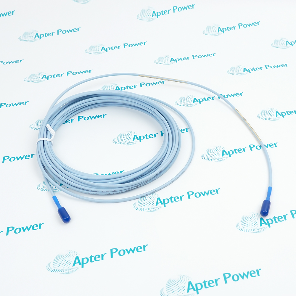
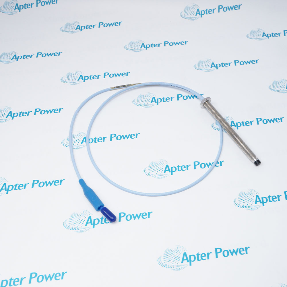
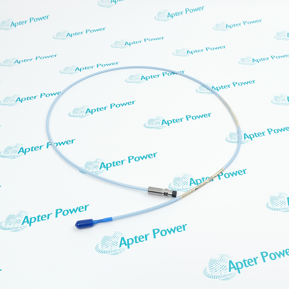
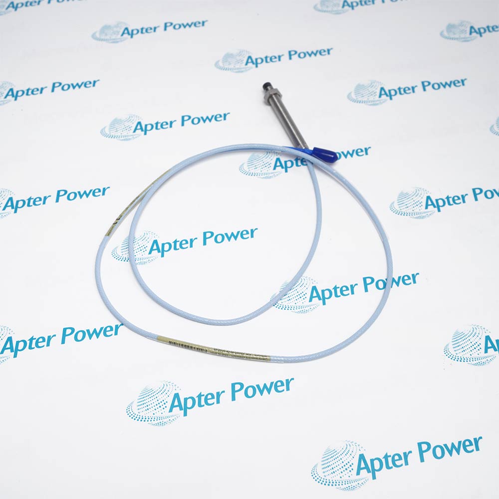
Request available label and terminal photos. Have your maintenance team compare the offered 330780-91-05 with the installed equipment and applicable Bently Nevada documentation.
Technical specifications for 330780-91-05
-
Manufacturer:Bently Nevada
-
Product Category:Machinery Monitoring Systems
-
Spare Part Number:330780-91-05
-
Weight:0.24 kg
-
Tariff Code:8537101190
-
Calibrated system length:9.0 m
-
Mounting:DIN mount
-
Transducer input:One 3300 XL 11 mm probe and extension cable
-
Supply without barriers:-17.5 to -26 V DC
-
Supply with barriers:-23 to -26 V DC
-
Maximum current consumption:12 mA
-
Output resistance:50 ohms
-
Supply sensitivity:Less than 2 mV output change per volt of supply change
-
Matched-system linear span:4.0 mm (160 mils)
-
Recommended gap:2.5 mm (100 mils)
-
Nominal scale factor:3.94 V/mm (100 mV/mil), +/-10%
-
Typical frequency response:0-8 kHz, +0/-3 dB
-
Field conductor range:0.2-1.5 mm2; 0.25-0.75 mm2 with ferrules
-
Maximum monitor field wiring:305 m; frequency-response conditions apply
-
Sensor operating temperature:-52 to +100 deg C
-
Sensor storage temperature:-52 to +105 deg C
Information
- Bently Nevada 330780-91-05 places the 11 mm transducer conditioning electronics on a DIN rail, connecting the calibrated 9 m probe circuit to three-conductor monitor field wiring.
Installation: DIN mounting; SpringLoc field terminals
Signal output: 50 ohm output resistance; nominal 3.94 V/mm system scale factor
The Proximitor Sensor accepts one probe circuit and conditions target-distance changes into a voltage signal. The matched 11 mm system has a nominal 4.0 mm linear span and 3.94 V/mm scale factor under its reference conditions, with a recommended 2.5 mm gap. The receiving monitor must use the corresponding scale rather than the 7.87 V/mm scale of an 8 mm system. Without barriers the supply range is -17.5 to -26 V DC, at up to 12 mA. With barriers the specified range is -23 to -26 V DC. A supply more positive than -23.5 V DC can reduce output headroom and usable linear range. The extended deviation-from-straight-line range is not applicable with zener barriers.
SpringLoc terminals accept 0.2-1.5 mm2 conductors, or 0.25-0.75 mm2 with ferrules. The output resistance is 50 ohms; field wiring can extend to 305 m under the specified response conditions. Typical system response is 0-8 kHz at +0/-3 dB. The conditioner operates from -52 to +100 deg C and stores up to +105 deg C, independently of the higher probe temperature limit.
330780-91-05 Official Technical Reference Excerpt
3300 XL 11 mm Proximity Transducer System, 146256 Rev. T: preserved manufacturer specifications applicable to this product configuration. PDF · 8 pages.330780-91-05 Installation & Verification Guide
Apter Power field guide for DIN mounting, negative supply and barrier checks, field wiring and calibrated-channel tests. PDF · 5 pages.
Application scope: Its voltage output supports configured vibration and position channels. A compatible probe, cable, target and monitor are required to apply the quoted system performance.
DIN-rail conditioning
Locate the conditioner in a suitable cabinet with access to field terminals and controlled temperature.Nine-metre sensor chains
Connect a matched 1 m probe and 8 m extension while preserving the calibrated total length.Long monitor connections
Carry the conditioned signal on shielded triad wiring with frequency response assessed for the actual route.Axial or radial monitoring
Feed a suitably configured monitor for thrust position or shaft-relative vibration within the system span.
Match 9 m system length; do not rely on housing similarity.
Secure the mounting pad and keep terminals accessible for inspection.
Measure supply polarity and voltage at the installed sensor before connecting the monitor.
Apply the barrier-specific voltage range and approved circuit limitations.
Do not count monitor field wiring as part of the probe-plus-extension length.
Check static gap voltage, controlled movement response and alarm behavior as one channel.
Alternative Names
Technical notes
Electrical-length boundary: The 9 m calibration concerns the probe and extension cable; monitor field wiring is outside that total.
Environmental boundary: Keep the Proximitor Sensor within -52 to +100 deg C even when the probe is in a hotter location.

FAQ View All FAQ
-
Does the 9 m calibration of 330780-91-05 include the monitor field wiring?No. The 9 m length is the probe lead plus compatible extension cable. The three-conductor wiring from the Proximitor Sensor to the monitor is a separate circuit.
-
Can 330780-91-05 operate with a 5 m probe-and-cable combination?A 5 m combination does not match this sensor's 9 m calibration. Use the correct 9 m chain or select a sensor calibrated for the required system length.
-
Why can the linear span of 330780-91-05 shrink near the positive supply limit?A supply more positive than -23.5 V DC can reduce output headroom and linear range. The nominal full-span reference uses -24 V DC; evaluate the actual supply and barrier voltage drop.
-
Which conductor sizes fit the field terminals of 330780-91-05?The specified range is 0.2-1.5 mm2 for field conductors, or 0.25-0.75 mm2 with ferrules. Three-conductor shielded triad cable is recommended for the monitor connection.
-
How does the 50 ohm output resistance of 330780-91-05 affect channel design?It is part of the output interface seen by the monitor and field wiring. Use the specified monitor load and account for cable capacitance when checking high-frequency response.
-
Can 330780-91-05 use the probe's +177 deg C temperature limit?No. The Proximitor Sensor operating limit is +100 deg C. The higher +177 deg C limit belongs to the probe and extension cable, so the conditioner must be located within its own rating.
-
What target and gap underpin the nominal response of 330780-91-05?The reference system uses the specified AISI 4140 steel target and a 2.5 mm gap. The nominal scale factor is 3.94 V/mm and the standard linear span is 4 mm under the stated conditions.
-
What changes when barriers are installed ahead of 330780-91-05?The specified supply range becomes -23 to -26 V DC with barriers. The extended deviation-from-straight-line range is not applicable with zener barriers; verify the approved barrier circuit and available voltage.
Supporting new and legacy automation
-
Please try to be as accurate as possible with your search.
-
We can quote you on 1000s of specialist parts, even if they are not listed on our website.
-
We can't find any results for “”.
You May Also Like
Product Browsing History
-
Whatsapp: +86 18030235313
Send us a message. -
sales13@apterpower.com
Complete our online form. -
+86 18030235313
Speak to our team in your native language.