-
Match the complete marking
Include 330173-00-06-10-02-00 and any revision or assembly number visible on the item. Keep the exact reference on your enquiry and quotation.
-
Check the offered item before ordering
Request available label and probe-connection photos. Have your maintenance team compare the offered 330173-00-06-10-02-00 with the installed equipment and applicable Bently Nevada documentation.
Technical specifications for 330173-00-06-10-02-00
-
Manufacturer:Bently Nevada
-
Product Category:Machinery Monitoring Systems
-
Spare Part Number:330173-00-06-10-02-00
-
Weight:0.04 kg
-
Tariff Code:8537101190
-
Probe family:3300 5 mm
-
Mounting thread:M8 x 1
-
Unthreaded length:0 mm
-
Overall case length:60 mm
-
Total probe length:1.0 m
-
Cable construction:Standard; without armor
-
Connector:Miniature coaxial ClickLoc
-
1.0 m probe DC resistance:7.59 +/- 0.50 ohms
-
Matched-system linear span:2 mm (80 mils)
-
Recommended gap:1.27 mm (50 mils)
-
Typical scale factor:7.87 V/mm (200 mV/mil), +/-6.5%
-
Matched-system frequency response:0-10 kHz; +0/-3 dB
-
Maximum M8 thread engagement:12 mm
-
Minimum cable bend radius:25.4 mm
-
Probe operating temperature:-35 to +177 deg C; pressure-seal caveat below -34 deg C
Information
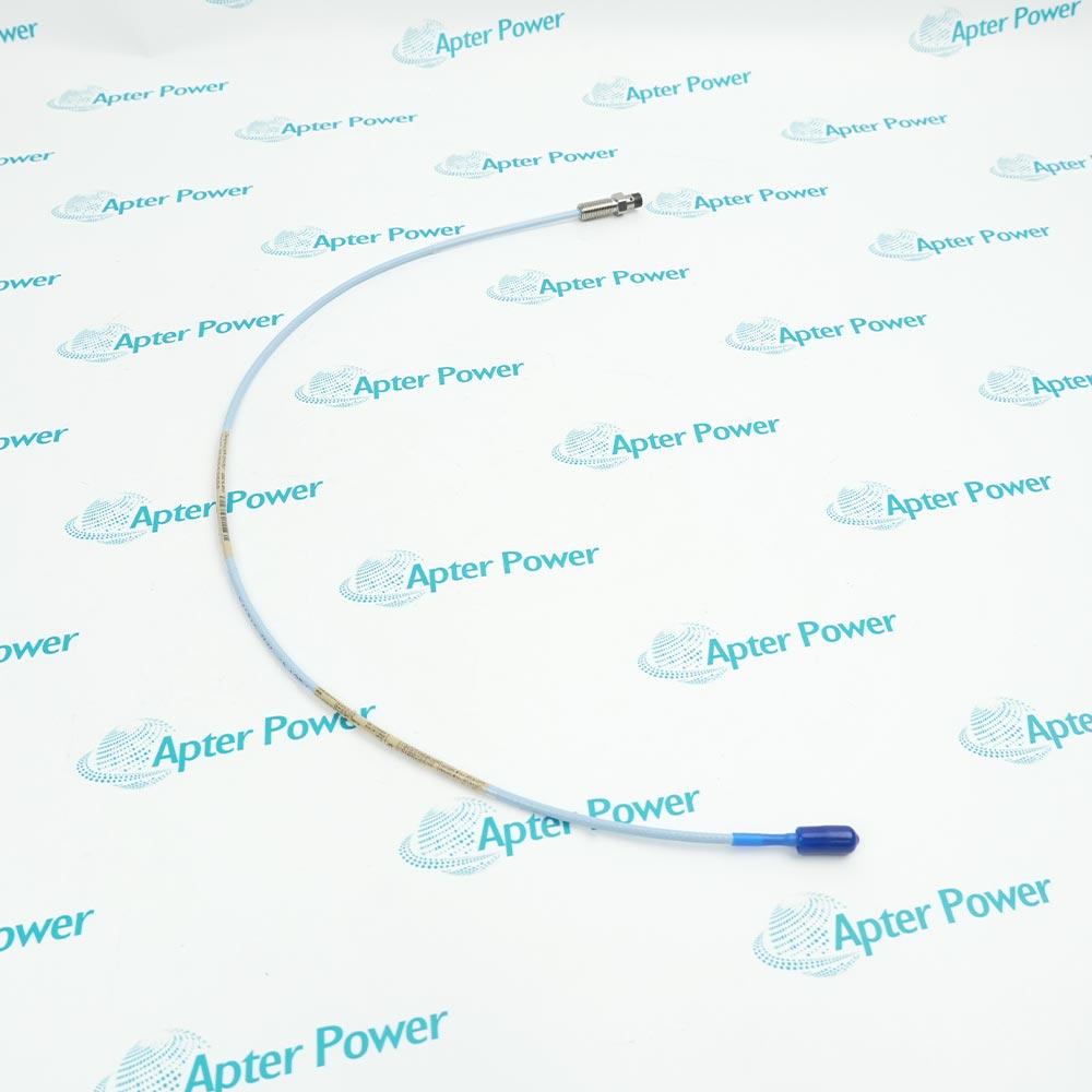
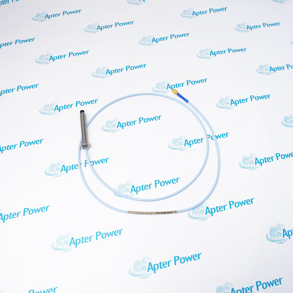
- The narrow probe construction of Bently Nevada 330173-00-06-10-02-00 suits metric mounting locations where the sensing tip must reach a shaft target through an M8 x 1 fitting.
Lead: 1.0 m standard cable; unarmored construction
Matched system: 2 mm linear span and nominal 7.87 V/mm scale factor
The 3300 5 mm probe combines with a compatible XL extension cable and Proximitor Sensor to form the calibrated measuring chain. The assembled system provides a 2 mm linear span and typical 7.87 V/mm scale factor with +/-6.5% incremental scale-factor tolerance. Reference conditions include an AISI 4140 target, -24 V DC supply, 10 kilohm load, 1.27 mm gap and +18 to +27 deg C temperature. The specified response extends from 0 to 10 kHz at +0/-3 dB under the field-wiring conditions. Target geometry also matters: the minimum shaft diameter is 50.8 mm and the recommended minimum is 76.2 mm. Smaller shafts and nearby probe targets can change scale factor or introduce cross-talk even when the electrical components are correctly matched.
M8 thread engagement is limited to 12 mm, and the cable requires a minimum bend radius of 25.4 mm. The disconnected 1.0 m probe has a nominal center-to-outer conductor resistance of 7.59 +/- 0.50 ohms. The probe operates from -35 to +177 deg C, but exposure below -34 deg C can cause premature pressure-seal failure; a resistance or temperature check alone does not establish containment integrity.
330173-00-06-10-02-00 Official Technical Reference Excerpt
3300 5 mm Transducer System, 172036 Rev. T: preserved manufacturer specifications applicable to this product configuration. PDF · 6 pages.330173-00-06-10-02-00 Installation & Verification Guide
Apter Power field guide for M8 mounting, lead protection, target geometry and calibrated gap-response checks. PDF · 5 pages.
Application scope: Use the assembled system for non-contact shaft-relative vibration or position channels. Probe-family performance does not establish compatibility with every monitor or target geometry.
Compact metric access
Reach a suitable shaft target through an M8 x 1 mounting arrangement using the narrow 5 mm family.Shaft-relative motion
Feed a matched monitoring channel for radial displacement measurements within the calibrated span.Position measurement
Observe controlled target displacement with a verified DC gap and the appropriate conditioner scaling.Existing 5 mm channel repair
Retain the 1 m lead and compatible electrical-length combination during a like-for-like probe replacement.
Confirm M8 x 1 fit, engagement and free clearance around the tip.
Do not cut, splice or use an arbitrary cable to extend the calibrated circuit.
Keep the unarmored lead above its 25.4 mm minimum bend radius.
Check shaft material, diameter and adjacent-probe separation before applying nominal performance.
Use the correct ClickLoc connection and protect the joint against contamination.
Measure gap response and confirm the monitor scaling and configured alarms before release.
Alternative Names
Technical notes
System relationship: The 1.0 m probe cable forms part of the calibrated electrical length with the extension and Proximitor Sensor.
Geometry boundary: Small shafts, adjacent probes and surrounding metal can affect sensitivity and cross-talk.

FAQ View All FAQ
-
What mounting geometry does the 00-06 selection give 330173-00-06-10-02-00?It specifies zero unthreaded length and a 60 mm overall case, using the 330173 M8 x 1 unarmored construction. The mating hardware must provide the correct thread fit and sensing-tip clearance.
-
Can 330173-00-06-10-02-00 use the same 4 mm measuring span as an 11 mm XL probe?No. The stated linear span for the matched 3300 5 mm system is 2 mm. An 11 mm XL system has different calibration and must not be substituted solely because connectors appear similar.
-
What is the recommended starting gap for 330173-00-06-10-02-00?The reference gap is 1.27 mm, or 50 mils. Set and verify the gap through the complete calibrated system and actual target material rather than by mechanical position alone.
-
How should the lead of 330173-00-06-10-02-00 be routed near a mounting bracket?Maintain at least the specified 25.4 mm cable bend radius, avoid sharp edges and keep strain off the probe exit and connector. The unarmored cable needs appropriate mechanical protection.
-
What electrical resistance helps check a disconnected 330173-00-06-10-02-00?The specified center-to-outer conductor DC resistance for the 1.0 m probe is 7.59 +/- 0.50 ohms. Use this as a continuity check, followed by a complete-system gap and response test.
-
How deep can 330173-00-06-10-02-00 engage a matching M8 threaded hole?The specified maximum engagement for M8 x 1 is 12 mm. Longer engagement can bind, so check the mating thread and installation drawing before fitting the probe.
-
Why must small shaft geometry be assessed for 330173-00-06-10-02-00?The system specifies a minimum shaft diameter of 50.8 mm and recommends at least 76.2 mm. Smaller targets and nearby probes can alter scale factor or increase cross-talk.
-
Which conditions underpin the quoted accuracy of 330173-00-06-10-02-00?The reference system uses an AISI 4140 steel target, -24 V DC, a 10 kilohm load, a 1.27 mm gap and a temperature of +18 to +27 deg C. Actual materials and operating conditions require verification.
Supporting new and legacy automation
-
Please try to be as accurate as possible with your search.
-
We can quote you on 1000s of specialist parts, even if they are not listed on our website.
-
We can't find any results for “”.
You May Also Like
Product Browsing History
-
Whatsapp: +86 18030235313
Send us a message. -
sales13@apterpower.com
Complete our online form. -
+86 18030235313
Speak to our team in your native language.