Speak to a sourcing specialist
sales13@apterpower.com
Get a quick price for 330103-00-07-05-02-CN
E-mail *
Mobile *
Company
Content *
Quantity *
Upload (gif, jpg, jpeg, png, bmp, doc, docx, xls, xlsx, ppt, pdf, csv)
For more information on how your data is processed and stored by Apterpower please read our privacy policy

What happens after you enquire

  • 1

    Requirement review

    We review the part number, quantity and delivery requirements and ask for any missing details.
  • 2

    Quotation and availability

    We confirm the proposed item, condition, availability, price and estimated lead time in the quotation.
  • 3

    Order confirmation and dispatch

    Once the quotation and purchasing details are agreed, your contact will coordinate the order and available dispatch information.

Technical specifications for 330103-00-07-05-02-CN

  • Manufacturer:
    Bently Nevada
  • Product Category:
    Machinery Monitoring Systems
  • Spare Part Number:
    330103-00-07-05-02-CN
  • Estimated shipping dimensions:
    1.8×1.5×69cm
  • Weight:
    0.06 kg
  • Tariff Code:
    8537101190
  • Counliy of origin:
    USA
  • Sensing principle:
    Non-contact eddy current
  • Probe tip diameter:
    8 mm
  • Mounting thread:
    M10 x 1
  • Unthreaded length:
    0 mm
  • Case length:
    70 mm
  • Total probe length:
    0.5 m
  • Cable construction:
    75 Ω triaxial, FEP insulation; unarmored
  • Nominal probe DC resistance:
    7.45 ± 0.50 Ω, center to outer conductor
  • Minimum cable bend radius:
    25.4 mm
  • Recommended standard forward-mount torque:
    11.2 N·m
  • Connector maximum torque:
    0.565 N·m
  • Probe case material:
    AISI 303 or 304 stainless steel
  • Probe tip material:
    PPS

Information

Overview Manuals Common Applications Product Precautions
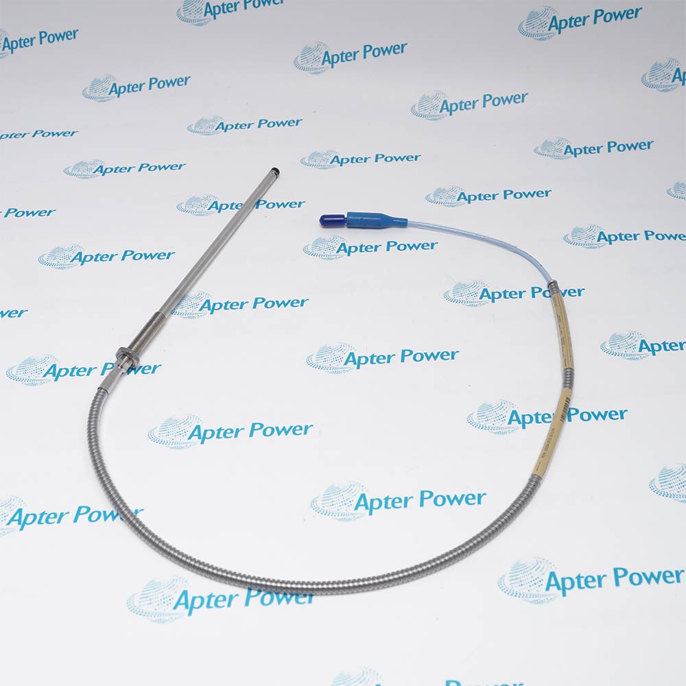
Bently Nevada 330103-00-07-05-02-CN places the sensing tip close to a conductive shaft while the Proximitor sensor converts the changing gap into a voltage for the monitoring channel.
  • Uses a PPS sensing tip bonded to its stainless-steel case.
  • Provides a gold-plated ClickLoc connection that locks when finger-tight.
  • Carries the probe signal through an FEP-insulated triaxial lead.
  • Supports interchangeable 3300 XL 8 mm system components.

The mounting bore must leave sufficient electromagnetic clearance around the tip. A small shaft or nearby metal can alter the scale factor even when the threaded case fits correctly; check the installed geometry before setting the operating gap.

Important Notice: Set and verify the probe gap after tightening the mounting hardware, then confirm that the channel retains adequate movement toward and away from the tip.

Bently Nevada 330103-00-07-05-02-CN Manuals & Downloads
Bently Nevada 330103-00-07-05-02-CN Official Technical Reference Excerpt (PDF)Bently Nevada 330103-00-07-05-02-CN Installation & Commissioning Guide (PDF)

The technical excerpt covers transducer construction and performance. The installation guide develops mounting, connection and signal-verification procedures for the selected assembly.


Radial shaft vibration
Sense shaft movement relative to a fluid-film bearing housing.
Static position
Track the average gap to a conductive target through a matched conditioner.
Phase reference
Provide a target passage signal for an appropriately configured Keyphasor channel.
Accessible cable junctions
Bring the short integral lead to a protected extension-cable joint near the measurement point.
Protect the measuring target, cable path and electrical connections when installing Bently Nevada 330103-00-07-05-02-CN.
1
Check that the mounting hole accepts M10 x 1 without forcing the case.
2
Keep nearby metal outside the required probe tip clearances.
3
Route the 0.5 m lead without stretching it to reach a remote junction.
4
Keep cable bends at or above the specified minimum radius.
5
Finger-tighten the ClickLoc connection and fit the required environmental protection.
6
Match probe plus extension length to the Proximitor electrical length.
7
Confirm the voltage-to-gap response on the actual target material.
8
Test channel indication and alarm response after the mechanical gap is secured.

Technical notes

Use a connector protector where the cable joint needs environmental protection. The standard cable option does not provide the FluidLoc liquid-blocking construction.

FAQ View All FAQ

  • What does a lead resistance of about 7.45 ohms confirm for 330103-00-07-05-02-CN?
    The disconnected 0.5 m probe has a nominal center-to-outer-conductor resistance of 7.45 ±0.50 Ω. That checks electrical continuity, but not its calibrated displacement response.
  • Can the M10 case tightening torque also be applied to the ClickLoc joint on 330103-00-07-05-02-CN?
    No. The standard forward-mounted case has a recommended 11.2 N·m torque, while the connector maximum is only 0.565 N·m. Assemble the ClickLoc joint finger-tight until it clicks.
  • Will 330103-00-07-05-02-CN retain its standard calibration against a different shaft alloy?
    The reference calibration uses AISI 4140 steel. A different alloy can change the voltage-to-gap relationship; establish the response on the actual target before applying the nominal scale factor.
  • Which extension length completes a five-metre channel with 330103-00-07-05-02-CN?
    Its 0.5 m probe length requires the corresponding 4.5 m extension cable and a five-metre Proximitor sensor. The assembled electrical length, rather than the 70 mm case length, determines that match.
  • What accuracy limitation remains if 330103-00-07-05-02-CN is connected through a compatible non-XL component?
    The assembled channel is limited to the applicable non-XL 3300 performance. The XL probe alone does not establish XL accuracy for the complete transducer system.
  • What physical gap does a -9 V radial-channel reading represent with 330103-00-07-05-02-CN?
    It corresponds to approximately 1.27 mm under the standard XL 8 mm reference conditions. Verify that the expected shaft motion stays within the usable linear interval on both sides of this operating point.
  • Does the standard cable in 330103-00-07-05-02-CN stop liquid from migrating inside the lead?
    No. Internal liquid blocking is a function of the separately selected FluidLoc construction. A connector protector addresses the joint environment and does not turn the standard cable into a FluidLoc cable.
  • How much routing space does the short lead of 330103-00-07-05-02-CN need at a bend?
    Maintain at least a 25.4 mm bend radius. Leave enough room at the case exit and connector to avoid a tighter bend or tension on the 0.5 m lead.
Related reading

Related cases and sourcing guidance

View all case studies
SPEAK TO OUR TEAM
Let’s find the right solution for you.
Send us the part number, quantity and delivery destination. Our team will help confirm availability and lead time.
  • Whatsapp: +86 18030235313

    Send us a message.
  • sales13@apterpower.com

    Complete our online form.
  • +86 18030235313

    Speak to our team in your native language.