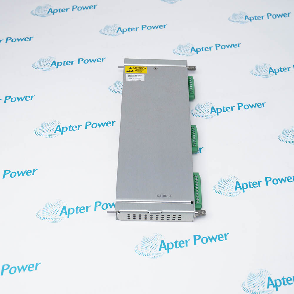
-
Match the complete marking
Include 21504-00-12-10-02 and the visible revision or assembly identity in your enquiry. Keep the full reference on the quotation. -
Check the offered item before ordering
Request available label and connector photos. Have your maintenance team compare the offered 21504-00-12-10-02 with the installed equipment and applicable Bently Nevada documentation.
Technical specifications for 21504-00-12-10-02
-
Manufacturer:Bently Nevada
-
Product Category:Machinery Monitoring Systems
-
Spare Part Number:21504-00-12-10-02
-
Weight:0.05 kg
-
Tariff Code:8537101190
-
Probe family:7200 Series 8 mm
-
Mounting thread:3/8-24 UNF
-
Lead armor:none
-
Unthreaded length:0.0 in
-
Overall case length:1.2 in
-
Integral lead:1.0 m nominal
-
Connector:miniature male coaxial
-
System length:match probe, extension cable and Proximitor
Information
- Bently Nevada 21504-00-12-10-02. The 21504 probe senses shaft-to-tip distance as the front end of a 7200 Series proximity transducer chain.
Monitor interface: Matched 7200 8 mm system supported by 1900/65A channels
Its 3/8-24 UNF case has a 0.0 in unthreaded section and a 1.2 in overall length. Options 10 and 02 select a nominal 1.0 m integral lead and miniature male coaxial connector. The manufacturer's 8 mm probe construction uses PPS, and the probe and extension-cable operating range is -34 °C to +177 °C.
A matched probe lead, extension cable and Proximitor form a 5 m or 9 m calibrated system. The documented 7200 system has a 2.0 mm (80 mil) linear range beginning about 0.25 mm from the target, a 7.87 V/mm (200 mV/mil) scale factor within its stated calibration conditions, and a 0 to 10 kHz frequency response with -5% at 10 kHz. These performance values describe the complete system.
-
Bently Nevada 21504-00-12-10-02 technical reference
Original manufacturer excerpt - PDF, 4 pages. The Bently Nevada 7200 probe ordering table defines the 21504 family and the 00 / 12 / 10 / 02 option sequence. -
Bently Nevada 21504-00-12-10-02 installation guide
Prepared by Apter Power - PDF, 5 pages. Installation checks, fitting and lead routing, commissioning and verification.
Compatibility scope: The 3/8-24 UNF case, 1.2 in overall length, unarmored 1.0 m lead and miniature male coaxial connector must match the installed bracket and extension cable. System performance belongs to the complete probe, cable and Proximitor chain.
-
Radial shaft vibration
At a bearing plane, observe a suitable shaft target for relative vibration. The matched 7200 channel converts changing clearance into the monitored dynamic signal. -
Axial shaft position
At an approved thrust-position point, follow axial motion against a suitable target. Probe travel and final gap must remain within the system measurement range. -
Mean shaft position
A configured channel can trend average shaft position in an appropriate bearing arrangement. The monitor and transducer calibration define the interpretation. -
Phase reference
A target feature can generate a phase reference when the installed monitor is configured for that function. Target geometry and gap determine signal quality.
Make the machine and monitor channel safe before adjusting the probe. Record the previous mounting depth and reference gap.
Check the 3/8-24 UNF opening and locknut against the installed bracket. Confirm that the 1.2 in case can be secured at the required depth.
Inspect the shaft target and expected movement envelope before setting the tip. Leave the specified clearance at the extremes of travel.
Route the unarmored 1.0 m lead clear of hot or sharp surfaces. Avoid tension at the probe exit and at the miniature coaxial connector.
Keep the miniature male coaxial connection clean and dry. Pair the probe with the specified extension cable and Proximitor for the intended total system length.
Set and verify the static gap under the approved procedure. Check the resulting channel voltage and signal response before machine release.
Alternative Names
Technical notes
Probe configuration: Options 00 / 12 / 10 / 02 select a flush section, 1.2 in case, nominal 1.0 m lead and miniature coaxial connector.
System boundary: Sensing performance applies to the calibrated probe, extension cable, Proximitor and target arrangement.
Technical reference: Bently Nevada 7200 Proximity Transducer Systems, 5 mm and 8 mm Technical/Ordering Information.

FAQ View All FAQ
-
Which sensing system uses 21504-00-12-10-02?It is a 7200 Series 8 mm proximity probe intended for a matched transducer chain.
-
What is the mounting thread on 21504-00-12-10-02?The 21504 standard-mount case uses a 3/8-24 UNF thread.
-
Does 21504-00-12-10-02 have an unthreaded section?The 00 option selects 0.0 in unthreaded length.
-
What case length is selected for 21504-00-12-10-02?The 12 option selects a 1.2 in overall case length.
-
How long is the lead on 21504-00-12-10-02?Code 10 selects a nominal 1.0 m integral probe lead.
-
Is the lead of 21504-00-12-10-02 armored?The 21504 probe family has no stainless steel lead armor.
-
Which connector is supplied on 21504-00-12-10-02?The final 02 selects a miniature male coaxial connector.
-
Does 21504-00-12-10-02 operate as a complete calibrated transducer alone?The probe requires the appropriate extension cable and 7200 Proximitor to form the calibrated measuring system.
Supporting new and legacy automation
-
Please try to be as accurate as possible with your search.
-
We can quote you on 1000s of specialist parts, even if they are not listed on our website.
-
We can't find any results for “”.
You May Also Like
Product Browsing History
-
Whatsapp: +86 18030235313
Send us a message. -
sales13@apterpower.com
Complete our online form. -
+86 18030235313
Speak to our team in your native language.