-
Match the complete marking
Retain 21500-00-28-10-02 exactly, including every zero and suffix, when comparing the supplied item with the installed assembly.
-
Check the offered item before ordering
Request current 21500-00-28-10-02 item and connection photos; compare the mechanical interface, included parts and measuring-chain requirements.
Technical specifications for 21500-00-28-10-02
-
Manufacturer:Bently Nevada
-
Product Category:Machinery Monitoring Systems
-
Spare Part Number:21500-00-28-10-02
-
Estimated shipping dimensions:1.3x1x68.5cm
-
Weight:0.04 kg
-
Tariff Code:8537101190
-
Base construction:21500
-
Transducer family:7200 proximity transducer system
-
Sensing tip diameter:5 mm
-
Tip construction:Fiberglass
-
Mounting type:Standard forward mount
-
Case thread:1/4-28
-
Unthreaded length:0.0 in (00)
-
Overall case length:2.8 in (28)
-
Nominal total probe length:1.0 m (10)
-
Total length tolerance:+0.25 / -0.10 m
-
Connector:Miniature male coaxial (02)
-
Lead armor:None
-
Coaxial cable impedance:95 ohms
-
Probe/extension operating limits:-34 to +177 deg C
-
Relative humidity:Up to 95%; noncondensing
-
System linear measuring span:80 mils (2.0 mm), with matched conditioner
-
System scale-factor accuracy:+/-4% calibrated as a system; +/-9.5% including interchangeability errors
Information
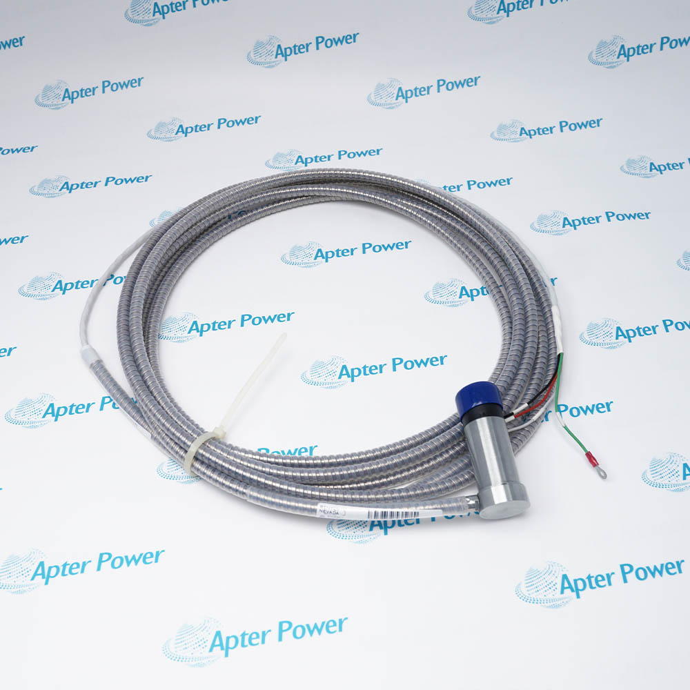
- For a compact machine mounting, Bently Nevada 21500-00-28-10-02 places a small-diameter sensing tip on a threaded case and carries excitation through its integral coaxial lead.
Case: Standard 1/4-28 mounting
Connection: Miniature male coaxial
The system can follow a steady target position as well as a changing shaft gap. Monitor selection and calibration determine how the conditioned signal is used.
Handle the tip and unarmored lead junction carefully during installation. A change of target material or chain component warrants another response check.
-
Bently Nevada 21500-00-28-10-02 technical reference
Original manufacturer excerpt - PDF, 4 pages. System architecture, operating limits, configuration and mounting information. -
Bently Nevada 21500-00-28-10-02 installation guide
Prepared by Apter Power - PDF, 5 pages. Pre-installation checks, wiring, adjustment, commissioning and fault isolation.
Platform applications: These applications describe the selected probe within a complete 7200 channel. Check the machine mounting, target and calibrated measuring chain before returning the channel to service.
-
Compact threaded mounting
Use the 1/4-28 standard case where the machine drawing calls for the selected 5 mm probe construction. -
Static gap monitoring
Observe a stationary or slowly changing conductive-target position through the matched 7200 conditioner. -
Dynamic displacement
Supply a gap-related signal for vibration-amplitude analysis using the appropriate monitor and reference channel. -
Rotor attitude assessment
Integrate the probe into an average radial-position channel when the machine monitoring arrangement requires shaft position information.
Confirm a 1/4-28 machine connection. Do not substitute a larger probe case solely because the monitoring purpose is similar.
Allow for the 2.8 inch case and 0.0 inch unthreaded section when comparing the installed geometry.
Use the miniature male coaxial connection selected by 02 and protect it against contamination and mechanical stress.
Include the nominal 1 m integral lead and its specified tolerance when checking the extension/conditioner combination.
Avoid mechanical abuse of the sensing face and unarmored cable junction; do not transfer 8 mm PPS corrosion ratings to this tip.
After component or target changes, verify gap and scale factor for the complete 7200 channel before monitoring service.
Alternative Names
Technical notes
Selected construction: The 00 / 28 / 10 / 02 sequence specifies 0.0 in unthreaded length, a 2.8 in case, a nominal 1 m total length and a miniature male coaxial connector.
Integration boundary: Use a matched 7200 extension-cable and Proximitor combination. The probe itself is not a standalone powered transmitter.
Technical reference: Bently Nevada 7200 Proximity Transducer Systems, 5 mm and 8 mm, L5001 (04/90).

FAQ View All FAQ
-
Which physical dimensions are selected by 00 and 28 in 21500-00-28-10-02?The 00 unthreaded-length option is 0.0 inches, and the 28 case-length option is 2.8 inches. These are probe construction dimensions; they are distinct from the package dimensions and the installed sensing gap.
-
What is the allowed lead-length tolerance for 21500-00-28-10-02?The 10 total-length option is nominally 1.0 m with a tolerance of +0.25 m and -0.10 m. Include this lead in the combined electrical-length check when selecting the extension cable and Proximitor.
-
Does the 02 suffix of 21500-00-28-10-02 identify a connector or an approval?The 02 connector option selects a miniature male coaxial connector. It does not identify a hazardous-area approval; installation approval must follow the actual component markings and approved circuit.
-
Can the case thread of 21500-00-28-10-02 be substituted for a 3/8-24 mounting?The 21500 standard case uses a 1/4-28 thread. A 3/8-24 mounting belongs to a different probe construction, so the machine mounting must be checked instead of treating the two threads as interchangeable.
-
Why must the 5 mm tip construction of 21500-00-28-10-02 be considered during handling?The 5 mm 7200 probe is constructed of fiberglass and has an unarmored lead. Protect the tip and coaxial junction during installation rather than applying the PPS-tip corrosion claims of the 8 mm construction.
-
How is accuracy assessed after a measuring-chain change involving 21500-00-28-10-02?The nominal system scale factor is 200 mV/mil. The specification allows +/-4% when calibrated as a system and +/-9.5% including interchangeability errors, so changing components is a reason to verify the complete response.
-
Can 21500-00-28-10-02 support both slow shaft-position and dynamic vibration measurements?A correctly matched 7200 chain responds from DC to 10 kHz and supports static gap as well as dynamic displacement. The stated high-frequency response is a system characteristic, not a standalone probe voltage output.
-
What does a channel-length mismatch do to an installation using 21500-00-28-10-02?The probe lead and extension cable must match the selected 5 m or 9 m Proximitor configuration. Selecting cable length from physical reach alone can create the wrong electrical chain and invalidate the intended calibrated response.
Supporting new and legacy automation
-
Please try to be as accurate as possible with your search.
-
We can quote you on 1000s of specialist parts, even if they are not listed on our website.
-
We can't find any results for “”.
You May Also Like
Product Browsing History
-
Whatsapp: +86 18030235313
Send us a message. -
sales13@apterpower.com
Complete our online form. -
+86 18030235313
Speak to our team in your native language.