Speak to a sourcing specialist
sales13@apterpower.com

1734-EP24DC

Expansion Power Supply
Ships by Saturday, November 7
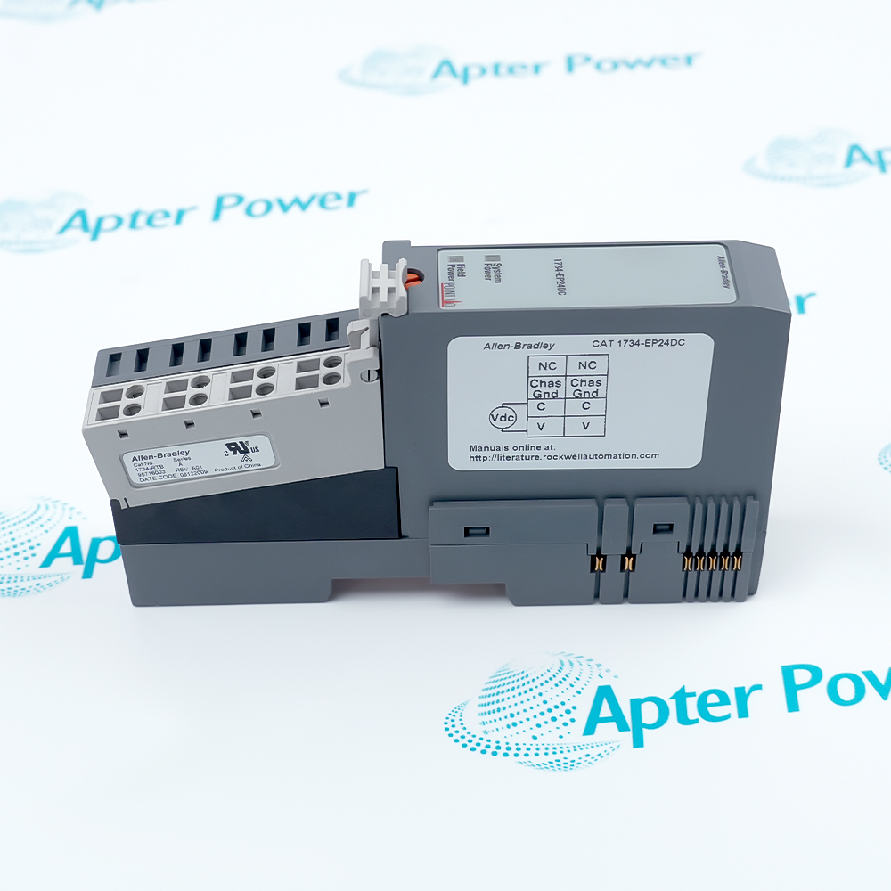
Allen-Bradley 1734-EP24DC (1)
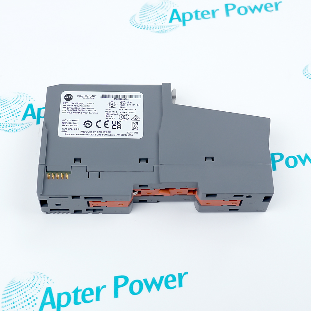
Allen-Bradley 1734-EP24DC (2)
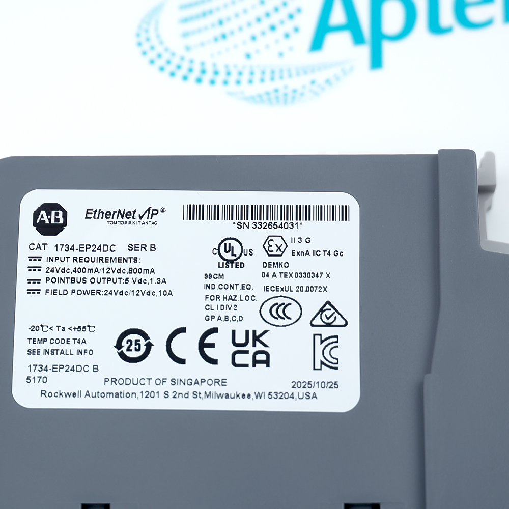
Allen-Bradley 1734-EP24DC (3)
Allen-Bradley 1734-EP24DC (1)
Allen-Bradley 1734-EP24DC (2)
Allen-Bradley 1734-EP24DC (3)
Product image is representative; revision or series may vary. Contact us to request a specific version.

Product Describe:

Allen-Bradley 1734-EP24DC is a POINT I/O expansion power supply that extends POINTBus power and creates a separate 24V DC field-power segment for modules to its right.
  • Manufacturer part number
    1734-EP24DC
  • Shipping
    Swift global dispatch
  • Condition
    New, original product
  • Shipping size (est.)
    13.2cm x 2.5cm x 7.5cm
  • Country of Origin
    USA
Get a quick price for 1734-EP24DC
E-mail *
Mobile *
Company
Content *
Quantity *
Upload (gif, jpg, jpeg, png, bmp, doc, docx, xls, xlsx, ppt, pdf, csv)
For more information on how your data is processed and stored by Apterpower please read our privacy policy

What happens after you enquire

  • 0

    Review your reference

    Send the complete 1734-EP24DC marking, hardware series and required quantity.

  • 1

    Confirm the offer

    Review the offered condition, removable terminal block, included documents and dispatch date.

  • 2

    Arrange dispatch

    Confirm delivery details, the lead-time start and shipment documents before arranging dispatch.

  • Match the complete marking

    Match 1734-EP24DC and its hardware series to the installed POINT I/O station; retain the complete catalog identity.

  • Check the offered item before ordering

    Review actual label, terminal-block and latch photos, and confirm the included parts and documents in the quotation.

Technical specifications for 1734-EP24DC

  • Manufacturer:
    Allen-Bradley
  • Product Category:
    PLC Systems
  • Spare Part Number:
    1734-EP24DC
  • Weight:
    0.15 kg
  • Tariff Code:
    8537101190
  • Product series:
    POINT I/O 1734
  • Module function:
    24V DC expansion power supply
  • Nominal input voltage:
    24V DC
  • Input voltage range:
    10 to 28.8V DC
  • Field-side input requirement:
    400 mA maximum at 24V DC
  • Maximum inrush current:
    6 A for 10 ms
  • POINTBus current, horizontal:
    1 A at 10 to 19.2V input; 1.3 A at 19.2 to 28.8V input
  • POINTBus current, vertical:
    1 A at 10 to 28.8V input
  • Field-power bus current:
    10 A maximum
  • I/O module capacity:
    4 to 17 modules, depending on each module current rating
  • Maximum power consumption:
    9.8 W at 28.8V DC
  • Maximum power dissipation:
    3.0 W at 28.8V DC
  • Isolation voltage:
    50V continuous; tested at 2600V DC for 60 s
  • Operating temperature:
    -20 to +55 °C
  • Relative humidity:
    5 to 95%, noncondensing
  • Terminal screw torque:
    0.6 N·m (7 lb·in)
  • Conductor range:
    22 to 14 AWG copper, rated at least 75 °C
  • Enclosure type:
    Open-style; suitable enclosure required
  • Status indicators:
    Green system-power and field-power indicators

Information

Overview Downloads Applications / Compatibility Product Precautions
  • Allen-Bradley 1734-EP24DC divides a POINT I/O station into manageable power segments. Plan its location where the downstream module-current budget or field-power grouping requires a new supply boundary.
Product type: POINT I/O expansion power supply
Nominal input voltage: 24 V DC
Field power: Independent downstream segment
POINTBus current: Mounting-dependent rating
The module passes field power to modules on its right while extending the backplane power available to that segment. Input and output groups, analog and digital groups, or modules serving a specific function can be partitioned.

Check the actual input voltage and orientation when calculating the POINTBus load. The field bus supports up to 10 A, while the backplane output has a separate 1 A or 1.3 A limit.
Controller platform reference: Allen-Bradley POINT I/O power expansion. Match the adapter, module loads and field-voltage segments.
Technical downloads for Allen-Bradley 1734-EP24DC: a manufacturer technical excerpt and an Apter Power installation and commissioning guide.
The technical reference preserves selected manufacturer pages. The installation guide is compiled by Apter Power for preparation and review; apply the original operating procedures and site controls during work.
Install Allen-Bradley 1734-EP24DC within its power, mounting and environmental limits. Isolate the relevant supplies and verify the downstream segment before commissioning.
Isolate the power sources

Remove applicable system and field power before installation, removal or rewiring. Do not connect 120/240V AC to the DC input; use a power source meeting the installation and regional requirements.

Calculate both power budgets

Calculate POINTBus demand and field-load demand separately. Observe the horizontal and vertical current limits; a 10 A field-power rating is not a 10 A POINTBus output rating.

Ground the DIN rail

Mount on grounded zinc-plated, chromate-passivated steel DIN rail and secure the rail and end anchors. The module grounding path depends on the rail contact.

Check the terminal assignments

Use terminals 6/7 for V, 4/5 for common and 2/3 for chassis ground; terminals 0/1 are not connected. Verify polarity and tighten terminal screws to 0.6 N·m.

Protect the open-style module

Use a suitable enclosure and keep the surrounding air between -20 and +55 °C. Protect against electrostatic discharge, condensation and contamination; hazardous locations require the applicable marked approvals and enclosure conditions.

Verify the downstream segment

Seat adjoining modules fully, cover the last exposed interconnection with the end cap and check system/field indicators. Prove the affected I/O functions under the site commissioning procedure before release.

Alternative Names

AB 1734-EP24DC 1734 EP24DC

Technical notes

Power relationship: The supply creates a new field-voltage segment and extends POINTBus power for modules to its right. Calculate field current separately from the backplane current budget.

Installation protection: Use a grounded steel DIN rail, appropriate enclosure and compliant DC source. Apply the output-current limit for the installed orientation and input voltage.

Technical reference: Rockwell Automation POINT I/O 24V DC Expansion Power Supply Installation Instructions, 1734-IN058M-EN-P, July 2026.


FAQ View All FAQ

  • What changes downstream when 1734-EP24DC is inserted in a POINT I/O station?
    It extends POINTBus power and starts a new field-voltage segment for the modules to its right. Field power is separated from modules to its left, allowing input/output, analog/digital or function-based partitioning.
  • How many modules can 1734-EP24DC supply?
    A segment can support 4 to 17 modules depending on their current requirements. Add the actual module currents and check the POINTBus output limit, adapter capacity and complete station configuration rather than assuming that every combination supports 17 modules.
  • Why does the mounting orientation affect the 1734-EP24DC current budget?
    Horizontal mounting allows 1 A at 10 to 19.2V input and 1.3 A at 19.2 to 28.8V input. Vertical mounting allows 1 A across the 10 to 28.8V input range. Size the downstream POINTBus load for the installed orientation and input voltage.
  • Does the 10 A rating of 1734-EP24DC describe its POINTBus output?
    No. The 10 A maximum applies to the field-power bus. POINTBus output is limited to 1 A or 1.3 A under the stated input-voltage and mounting conditions; calculate these two loads separately.
  • Which terminals are used to continue power through 1734-EP24DC?
    Terminals 6 and 7 are the positive DC supply, terminals 4 and 5 are common, and terminals 2 and 3 are chassis ground. Terminals 0 and 1 are not connected. Check polarity, the field-voltage requirements of downstream modules and terminal torque before energizing.
  • What should the power indicators on 1734-EP24DC show during normal operation?
    The system-power and field-power indicators are steady green during normal operation. An off indicator means power is not applied to that function. Check the incoming supply, terminal connections and affected power segment before investigating downstream I/O behavior.
  • What identification and included items should be checked before ordering 1734-EP24DC?
    Request current label and terminal-block photos, and confirm the catalog number and hardware series against the installed station. Have the removable terminal block and any separately requested accessories or documents itemized in the quotation; the conformal-coated 1734-EP24DCK is a different catalog selection.
  • How are availability and dispatch confirmed for an order of 1734-EP24DC?
    Confirm the required quantity, offered condition and dispatch date in the quotation. Agree when the lead time starts and which inspection records, accompanying documents and warranty terms apply before approving the order; product lifecycle status does not establish seller stock.
Related reading

Related cases and sourcing guidance

View all case studies
SPEAK TO OUR TEAM
Let’s find the right solution for you.
Send us the part number, quantity and delivery destination. Our team will help confirm availability and lead time.
  • Whatsapp: +86 18030235313

    Send us a message.
  • sales13@apterpower.com

    Complete our online form.
  • +86 18030235313

    Speak to our team in your native language.