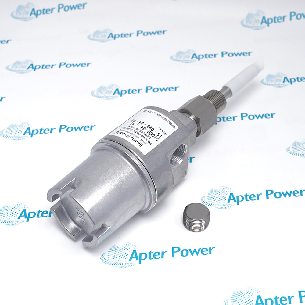
-
Match the complete marking
Compare every order group of 21000-33-10-00-070-04-02 with the installed item and the applicable Bently Nevada system documentation.
-
Check the offered item before ordering
Request photos of the offered 21000-33-10-00-070-04-02 and included items. Have the maintenance team compare them with the installed equipment and applicable Bently Nevada documentation.
Technical specifications for 21000-33-10-00-070-04-02
-
Manufacturer:Bently Nevada
-
Product Category:Machinery Monitoring Systems
-
Spare Part Number:21000-33-10-00-070-04-02
-
Weight:1.05 kg
-
Tariff Code:8537101190
-
Housing family:21000 aluminum assembly
-
Probe option:33: 3300 XL 8 mm with connector protector
-
Probe cable:10: 1.0 m
-
Standoff adapter:00: none
-
Probe penetration:070: 7.0 in
-
Fitting option:04: one 3/4-14 NPT plug
-
Mounting thread:02: 3/4-14 NPT
-
Enclosure elements:Dome cover, threaded conduit ports, probe sleeve and seals
-
Probe chain:Match supplied probe to appropriate extension cable and 8 mm sensor
Information
- The 21000 assembly places a proximity probe through the machine case while housing its external cable junction.
Installed geometry: 7.0 in penetration; no standoff adapter
Fitting interface: 3/4-14 NPT mounting; single 3/4-14 NPT plug
Group 00 omits a standoff adapter, while 070 specifies 7.0 in nominal probe penetration. The source calls for sleeve support when C plus D exceeds 12 in; for this configuration compare actual installed support, side-view clearance and the shaft target before setting the gap.
Group 04 supplies a single 3/4-14 NPT plug and group 02 selects 3/4-14 NPT mounting thread. Do not infer a hazardous-area enclosure rating from a fitting name: the datasheet distinguishes the CA variants and actual approval configuration.
-
21000-33-10-00-070-04-02 | Official Bently Nevada Family Datasheet Excerpt
Official Bently Nevada datasheet excerpt - PDF, 5 pages. Selected original pages from 141600 Rev. AC cover the applicable product family and design limits. -
21000-33-10-00-070-04-02 Installation & Commissioning Guide
Apter Power engineering guide - PDF, 4 pages. Complete-code checks, readiness, replacement sequence, commissioning, fault isolation and handover.
Electrical role: The selected probe still requires a compatible extension cable and 8 mm Proximitor Sensor for a calibrated chain.
-
External shaft measurement
Verify mounting thread, penetration and shaft target clearance before installation. -
Housing service
Inspect dome cover, seals and conduit ports before closing the assembly. -
Probe-chain renewal
Confirm the 1.0 m probe lead and separately selected extension cable/sensor. -
Fitting review
Verify the single plug and the site conduit/sealing design against the approved drawing.
Compare every group of 21000-33-10-00-070-04-02 with the installed housing and source drawing.
Inspect the actual insertion and sleeve support to avoid probe movement or resonance.
Confirm case thread, target clearance and gap adjustment without tip contact.
Inspect cover, O-rings, conduit port and specified plug against site requirements.
Use actual CA/agency markings and the site drawing to assess hazardous-area suitability.
Record probe, extension cable, sensor and monitor channel before energization.
Alternative Names
Technical notes
Code map: AA selects probe option, BB cable, CC standoff, DDD penetration, EE fittings and FF mounting thread.
Mechanical boundary: The 7.0 in penetration must be checked against the machine case and target; the housing alone does not define final gap.
Technical reference: Bently Nevada 21000, 24701, and 164818 Proximity Probe Housing Assemblies Datasheet, 141600 Rev. AC.

FAQ View All FAQ
-
How should the installed probe assembly be compared with 21000-33-10-00-070-04-02?Compare all six groups, photos of the offered housing and probe, and the original drawing; nominal housing family alone is insufficient.
-
What can make 21000-33-10-00-070-04-02 unsuitable even when its mounting thread fits?Penetration, sleeve support, probe target and conduit route may differ. Check these mechanical interfaces before installation.
-
How is the probe chain completed for 21000-33-10-00-070-04-02?Identify the included 8 mm probe and 1.0 m lead, then select a matching extension cable and 8 mm Proximitor Sensor for the intended system length.
-
Why should sleeve support be reviewed for 21000-33-10-00-070-04-02?Long insertion can allow movement or resonance. Compare the actual C plus D dimension and installed support against the manufacturer guidance.
-
Does the fitting group of 21000-33-10-00-070-04-02 establish an explosion-proof rating?No. Assess the actual housing version, approval marking, fitted components and site drawing together; the source treats CA housing approvals separately.
-
What seals and closures should be inspected on 21000-33-10-00-070-04-02?Inspect the dome cover, O-rings, thread seal, plug and conduit interfaces before closing the assembly.
-
How should the probe gap be accepted after fitting 21000-33-10-00-070-04-02?Set the gap using the approved machine procedure and matched transducer chain, then record static output and controlled response.
-
What should be recorded when 21000-33-10-00-070-04-02 is handed over?Keep photos of the full marking, housing/fitting contents, mounted penetration, probe chain and monitored acceptance result.
Supporting new and legacy automation
-
Please try to be as accurate as possible with your search.
-
We can quote you on 1000s of specialist parts, even if they are not listed on our website.
-
We can't find any results for “”.
Related cases and sourcing guidance
View all case studiesYou May Also Like
Product Browsing History
-
Whatsapp: +86 18030235313
Send us a message. -
sales13@apterpower.com
Complete our online form. -
+86 18030235313
Speak to our team in your native language.