-
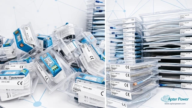
Match the complete marking
Include 16710-17 and every revision or approval marking visible on the item. Keep the exact reference on your enquiry and quotation. -
Check the offered item before ordering
Request available label and interface photos. Have your maintenance team compare the offered 16710-17 reference with the installed equipment and applicable Bently Nevada documentation.
Technical specifications for 16710-17
-
Manufacturer:Bently Nevada
-
Product Category:Machinery Monitoring Systems
-
Spare Part Number:16710-17
-
Weight:0.42 kg
-
Tariff Code:8537101190
-
Cable family:16710 armored accelerometer cable
-
Selected length:17 ft (approximately 5.0 m)
-
Conductor count:3 conductors
-
Conductor size:22 AWG (0.5 mm2)
-
Shielding:Shielded
-
Mechanical protection:Armored
-
Sensor-end termination:3-socket plug
-
Monitor-end termination:Terminal lugs
-
Supported sensors:330400 and 330425 accelerometers
-
Orderable cable range:3 to 99 ft
-
Ordering increment:1 ft
-
Companion sensor supply:-24 +/-0.5 V DC; 2 mA nominal bias current
-
Companion sensor output bias:-8.5 +/-0.5 V DC
-
Companion system max field cable:305 m without signal degradation
Information
- Bently Nevada 16710-17 is a 17 ft armored, shielded three-conductor cable for 330400 and 330425 casing-acceleration transducers.
Signal construction: Three shielded 22 AWG conductors.
Termination: Three-socket accelerometer plug to terminal lugs.
The cable uses three shielded 22 AWG conductors with armor, a three-socket sensor plug and terminal lugs at the receiving end. Preserve conductor identity, shield termination and armor support during replacement.
Cable acceptance is performed with the channel isolated: inspect the plug and lugs, verify each conductor end to end, reconnect to the approved wiring drawing and prove the returned casing-acceleration signal.
-
Bently Nevada 16710-17 official technical excerpt
Selected manufacturer pages covering the applicable family, technical data and exact order-code fields. -
Bently Nevada 16710-17 engineering guide
Apter Power installation, configuration, diagnostic and acceptance guidance.
Platform applications: The uses below require the documented 330400 and 330425 accelerometer interconnect cabling companion components and approved machine drawing.
-
330400 acceleration channel
Connect a 330400 100 mV/g accelerometer to its assigned casing-vibration monitoring input. -
330425 acceleration channel
Connect a 330425 25 mV/g accelerometer where the higher 75 g peak measurement range is required. -
Gear-mesh monitoring
Carry the wide-band casing-acceleration signal from the approved gear or bearing-housing mounting location. -
Installed cable replacement
Match the 17 ft length, three-socket plug, terminal lugs, conductor map, shield and armor route.
Place the accelerometer input in the approved maintenance state before opening terminal lugs or checking continuity.
Record every lug position and shield termination before removing the existing cable.
Keep the sensor connector dry and clean and do not use it as a pulling or support point.
Maintain route clearance, abrasion protection and independent strain relief at both terminations.
Test each conductor and check for unintended conductor-to-shield or conductor-to-armor paths.
After reconnection compare bias and controlled acceleration response with the accepted machine baseline.
Alternative Names
Technical notes
Sensor relationship: Use the three-socket plug only with the documented 330400 or 330425 accelerometer channel.
Signal path: Preserve the three-conductor map and the approved shield termination between the sensor and monitoring input.
Length selection: The -17 suffix selects 17 ft, approximately 5.0 m, within the manufacturer 3 to 99 ft ordering range.

FAQ View All FAQ
-
How should conductor identity be preserved when replacing 16710-17?Label all three conductors and terminal lugs before removal, then verify the sensor-plug pin map against the approved channel drawing.
-
How is a shield fault distinguished from an open conductor on 16710-17?With both ends isolated, test each conductor end to end and separately check conductor-to-shield and shield-to-armor paths.
-
Why must the armor of 16710-17 not be treated as signal return?The armor provides mechanical protection; using it as an electrical return can introduce ground paths and invalidate the documented shield scheme.
-
How should the three-socket plug on 16710-17 be inspected?Check socket retention, contamination, keying and strain relief, and confirm that cable movement does not disturb sensor bias.
-
What route checks apply before installing 16710-17?Confirm the 17 ft route reaches without tension, avoids abrasion and heat, and provides independent armor support at both ends.
-
How is monitor-end polarity checked for 16710-17?Use the approved terminal schedule and confirm conductor identity before reconnecting; do not derive polarity from insulation color alone.
-
What proves the accelerometer channel after replacing 16710-17?Verify stable sensor bias and compare the controlled casing-acceleration signal and monitor indication with the accepted baseline.
-
What handover record is required for 16710-17?Retain label photos, conductor and terminal map, shield treatment, continuity and insulation results, final route and channel proof.
Supporting new and legacy automation
-
Please try to be as accurate as possible with your search.
-
We can quote you on 1000s of specialist parts, even if they are not listed on our website.
-
We can't find any results for “”.
Related cases and sourcing guidance
View all case studiesYou May Also Like
Product Browsing History
-
Whatsapp: +86 18030235313
Send us a message. -
sales13@apterpower.com
Complete our online form. -
+86 18030235313
Speak to our team in your native language.