-
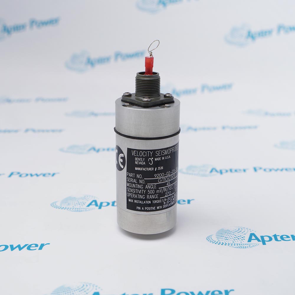
Match the complete marking
Compare 106765-07 with the installed cable label and the applicable Bently Nevada 330525 system documentation.
-
Check the offered item before ordering
Request photos of the offered 106765-07 cable and terminations. Have the maintenance team compare them with the installed route and applicable Bently Nevada documentation.
Technical specifications for 106765-07
-
Manufacturer:Bently Nevada
-
Product Category:Machinery Monitoring Systems
-
Spare Part Number:106765-07
-
Weight:0.62 kg
-
Tariff Code:8537101190
-
Cable family:106765 interconnect cable
-
Order length:07: 7 m
-
Sensor interface:330525 Velomitor XA
-
Sensor-end connection:Two-pin plug with splash-resistant boot
-
Cable conductors:Two-conductor, 22 AWG
-
Shield:Shielded cable; separate SHLD lead
-
Protective construction:FEP-coated stainless-steel armor
-
Field termination:White A, black B, green SHLD leads
-
Length range in source:1–25 m; 3 m order increments
Information
- This cable links the 330525 Velomitor XA sensor to the field wiring while protecting the sensor connection.
Sensor end: two-pin connection and splash-resistant boot
Field end: A, B and SHLD termination leads
The cable drawing identifies a two-pin connection at the sensor end and a fluorosilicone splash-resistant boot with clamps. FEP-coated stainless-steel armor protects the cable, while the two-conductor shielded lead continues to the field termination. Keep bend radius, clamp fit and sealing condition within the site installation practice.
At the field end, the identified conductors are A (white), B (black) and SHLD (green). Maintain the original terminal map and shield arrangement, then compare the measured channel response with the recorded baseline. A continuity check alone does not prove the installed sensor-monitor path.
-
106765-07 Official Bently Nevada Datasheet Excerpt
Original manufacturer pages - PDF, 3 pages. Applicable family design, system relationship, interface and technical drawing. -
106765-07 Installation & Commissioning Guide
Apter Power engineering guide - PDF, 4 pages. Exact configuration checks, replacement sequence, diagnostics and acceptance record.
Replacement boundary: Match length, sensor connector, boot and terminal identities.
-
Sensor cable replacement
Compare the 7 m route, connector and installed harness before removal. -
Weather-exposed installation
Inspect the boot and clamp seating at the sensor end. -
Field termination
Restore A, B and SHLD to the documented terminal arrangement. -
Channel acceptance
Check wiring continuity and controlled vibration response after installation.
Check 106765-07 on the offered label and compare its 7 m route.
Inspect the two-pin fit and splash-resistant boot before fastening.
Look for FEP coating damage, crushed cable or exposed shield.
Record A, B and SHLD before disconnecting the existing cable.
Avoid sharp bends, hot surfaces and moving machine parts.
Verify monitored response under an approved machine test after reconnection.
Alternative Names
Technical notes
Order-code meaning: The 07 suffix is the 7 m cable-length selection in the 106765 family.
Sensor interface: The cable is specified for the 330525 Velomitor XA sensor; verify the actual sensor marking and connector.
Technical reference: Bently Nevada 330525 Velomitor XA datasheet 141633 Rev. M.

FAQ View All FAQ
-
What does the 07 suffix in 106765-07 select?It identifies the 7 m ordered cable length. Compare the physical cable label and installed route before replacement.
-
How does 106765-07 connect at the 330525 sensor?The cable uses a two-pin connection with a splash-resistant boot and clamps. Inspect connector fit and sealing after assembly.
-
Which conductors must be mapped when replacing 106765-07?Record A (white), B (black) and SHLD (green) against the original field drawing before disconnecting the old cable.
-
What damage checks matter for 106765-07?Inspect armor, FEP coating, boot, clamps and cable bends; damaged protection can compromise the installed path.
-
Can 106765-07 be treated as the 330525 sensor itself?No. It is the interconnect cable; identify the sensor, cable and terminal housing separately in the quotation and installation record.
-
How should 106765-07 be routed near the machine?Follow the approved cable route, maintain bend clearance and protect it from moving or hot surfaces. Compare the 7 m length with the installed path.
-
Why is continuity alone insufficient to accept 106765-07?Continuity does not prove conductor mapping, shield termination or sensor response. Check the channel under an approved machine test.
-
What handover record is needed after installing 106765-07?Keep the complete cable marking, sensor identity, terminal map, routing photos and monitored acceptance result.
Supporting new and legacy automation
-
Please try to be as accurate as possible with your search.
-
We can quote you on 1000s of specialist parts, even if they are not listed on our website.
-
We can't find any results for “”.
Related cases and sourcing guidance
View all case studiesYou May Also Like
Product Browsing History
-
Whatsapp: +86 18030235313
Send us a message. -
sales13@apterpower.com
Complete our online form. -
+86 18030235313
Speak to our team in your native language.