Speak to a sourcing specialist
sales13@apterpower.com

1769-PB4

DC Power Supply
In Stock
Ships by Monday, November 9
Fast Shipping Available
AB 1769-PB4 (1)
AB 1769-PB4 (2)
AB 1769-PB4 (3)
AB 1769-PB4 (1)
AB 1769-PB4 (2)
AB 1769-PB4 (3)
Product image is representative; revision or series may vary. Contact us to request a specific version.

Product Describe:

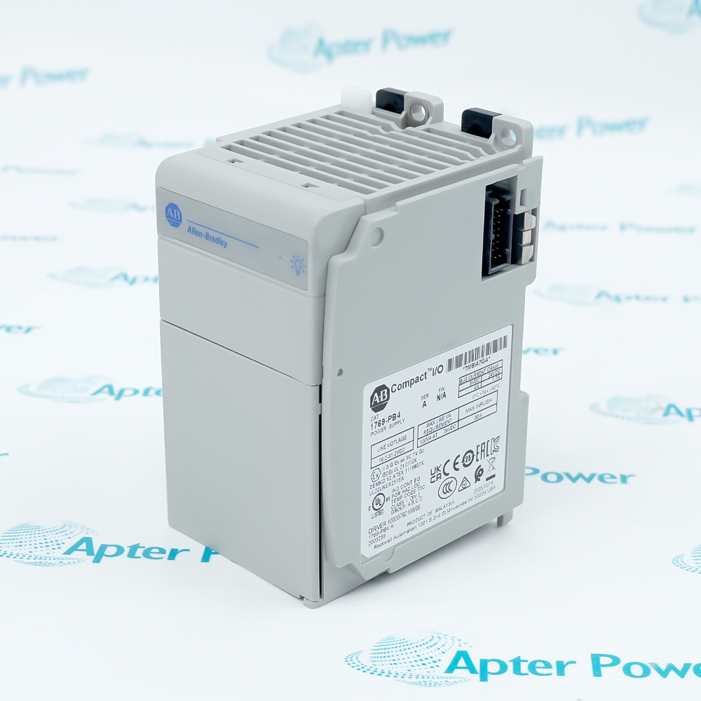
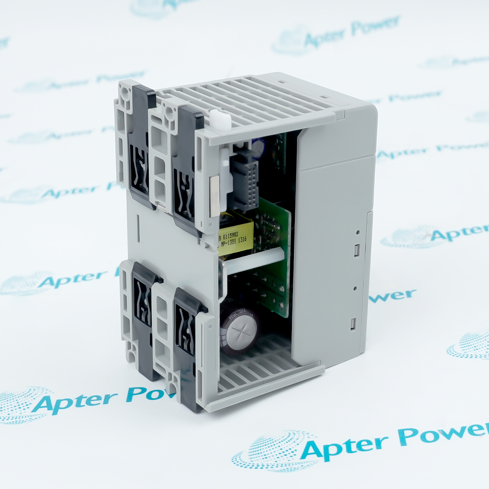
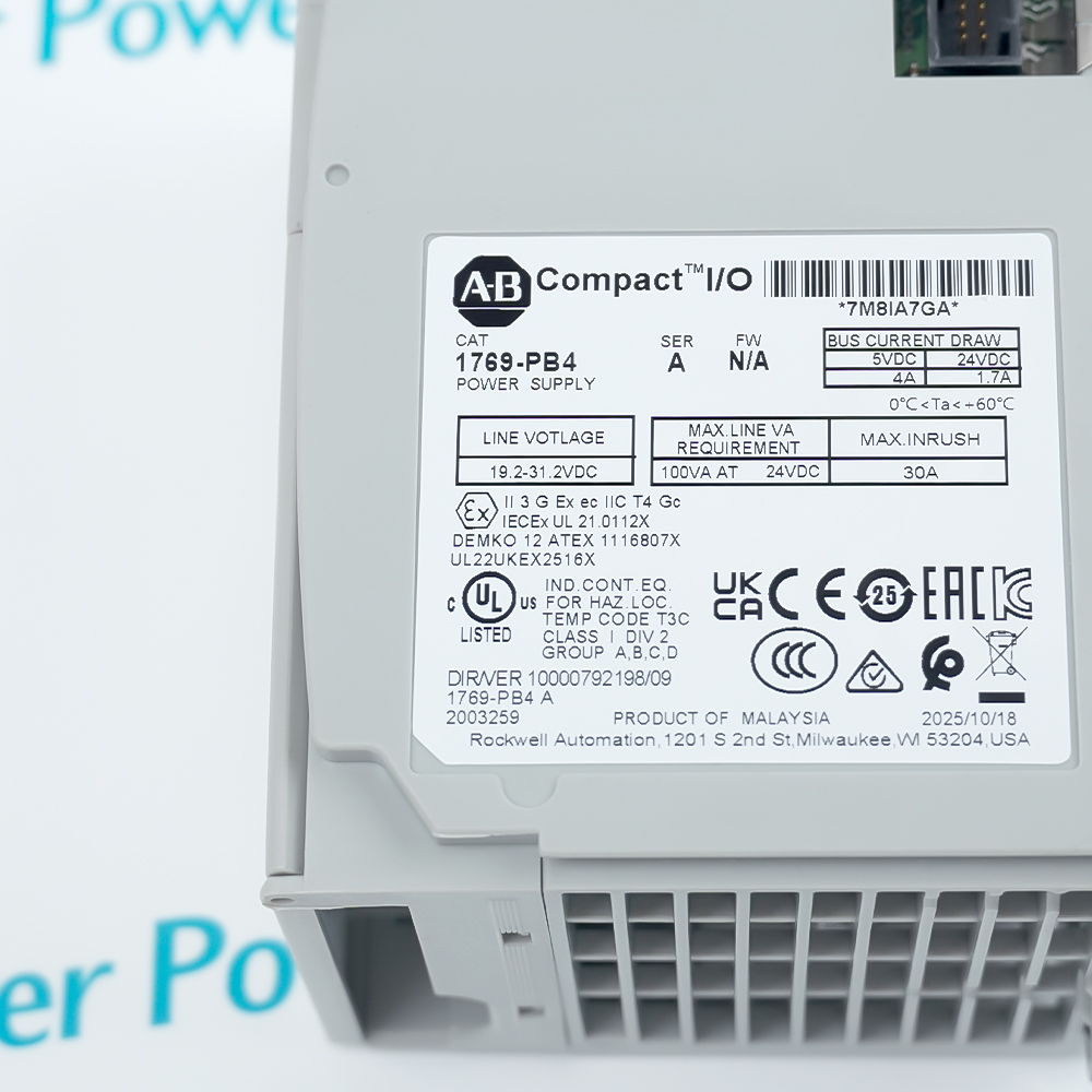
Allen-Bradley 1769-PB4 is a 24 V DC Compact I/O power supply that delivers regulated 5 V and 24 V backplane power to a 1769 module bank.
Get a quick price for 1769-PB4
E-mail *
Mobile *
Company
Content *
Quantity *
Upload (gif, jpg, jpeg, png, bmp, doc, docx, xls, xlsx, ppt, pdf, csv)
For more information on how your data is processed and stored by Apterpower please read our privacy policy

What happens after you enquire

  • 1

    Requirement review

    We review the part number, quantity and delivery requirements and ask for any missing details.
  • 2

    Quotation and availability

    We confirm the proposed item, condition, availability, price and estimated lead time in the quotation.
  • 3

    Order confirmation and dispatch

    Once the quotation and purchasing details are agreed, your contact will coordinate the order and available dispatch information.

Technical specifications for 1769-PB4

  • Manufacturer:
    Allen-Bradley
  • Product Category:
    PLC Systems
  • Spare Part Number:
    1769-PB4
  • Estimated shipping dimensions:
    7.3×8.6×13cm
  • Weight:
    0.34 kg
  • Tariff Code:
    8537101190
  • Counliy of origin:
    USA
  • Nominal input:
    24 V DC
  • Input voltage range:
    19.2–31.2 V DC
  • 5 V output current:
    4 A maximum
  • 24 V output current:
    2 A maximum; at 60 °C, 1.7 A with a 4 A load on the 5 V rail
  • Combined output power:
    68 W through 55 °C; 61 W at 60 °C
  • Power consumption:
    100 VA at 24 V DC
  • Maximum inrush:
    30 A at 31.2 V DC
  • Power dissipation:
    14.5 W at 60 °C
  • Continuous isolation:
    75 V; reinforced insulation
  • I/O bank capacity:
    Up to 8 modules per side, 16 total
  • Operating temperature:
    0–60 °C
  • Storage temperature:
    −40–85 °C
  • Relative humidity:
    5–95%, noncondensing
  • Mounting:
    DIN rail or panel

Information

Overview Manuals Common Applications Product Precautions
Allen-Bradley 1769-PB4 supports a centrally located power source in a Compact I/O assembly, allowing expansion modules on both sides within their permitted distance ratings.
  • Accepts a 19.2–31.2 V DC input supply.
  • Provides up to 4 A on the 5 V backplane rail.
  • Supports up to eight I/O modules on each side of the supply.
  • Attaches to a DIN rail or a grounded panel.

The module bank must satisfy both individual rail-current limits and the combined output-power limit. Ambient temperature changes the available 24 V output capacity, so bank loading should be calculated at the highest enclosure temperature.

Important Notice: Remove upstream power before assembling the bus connectors. Recheck every module distance rating and the bank current budget before energizing.

Allen-Bradley 1769-PB4 Manuals & Downloads
Allen-Bradley 1769-PB4 Manufacturer Technical Reference — Selected Pages (PDF)Allen-Bradley 1769-PB4 Installation & Commissioning Guide (PDF)

Use the technical reference for ratings and interface details, and the field guide for installation sequence, commissioning and fault isolation.


Compact I/O expansion
Provides backplane energy for a 1769 I/O bank assembled within module-count and distance constraints.
DC-fed control panels
Uses an existing nominal 24 V control-power source without an AC-input supply at the bank.
Mixed I/O banks
Supports separate current accounting for digital and analog modules drawing different proportions from the two rails.
Distributed I/O cabinets
Supplies a local Compact I/O bank where the selected controller or communication adapter supports that architecture.
Installation and service checks for Allen-Bradley 1769-PB4.
1
Isolate and verify the upstream DC supply before touching the terminals.
2
Check DC polarity and confirm the input remains within 19.2–31.2 V.
3
Keep protective earth connected to the grounded mounting system.
4
Position every I/O module within its own power-supply distance rating.
5
Lock the bus levers and fit the required bank end cap.
6
Calculate rail currents and combined power at the maximum ambient temperature.
7
Use the specified copper conductors and tighten connections to their designated torque.
8
Check supply indication and I/O operation under normal bank load before release.

Technical notes

Budget the 5 V and 24 V rails separately, then verify their combined load against the temperature-dependent power curve. Protective earth must remain continuous through the mounted assembly.

FAQ View All FAQ

  • How does ambient temperature change the 24 V output capacity of 1769-PB4?
    At 60 °C, a full 4 A load on the 5 V rail limits the 24 V rail to 1.7 A. A 2 A load on the 24 V rail is possible only with the 5 V load reduced to 2.6 A or less, within the 61 W combined limit.
  • Can 1769-PB4 deliver its full 5 V and 24 V ratings simultaneously?
    Both rail-current limits and the combined output-power ceiling apply. Add the power consumed on each rail and keep the total within 68 W through 55 °C or 61 W at 60 °C.
  • Where can I/O modules be positioned relative to 1769-PB4?
    Up to eight modules may be installed on each side, with no more than sixteen total. An individual module with a shorter power-supply distance rating must remain within that shorter distance.
  • Which DC input limits must the upstream supply meet for 1769-PB4?
    The input must remain between 19.2 and 31.2 V DC. A nominal 24 V source must also accommodate the connected bank load and startup demand.
  • Why should a 1769-PB4 power circuit be checked for startup inrush?
    The maximum inrush is 30 A at 31.2 V DC. Source capacity and protective-device characteristics must accommodate this transient without causing an unintended dropout.
  • Does 1769-PB4 provide an enclosure for the complete I/O assembly?
    The supply is open-style equipment. It must be installed within an enclosure suitable for the operating environment and protected against accidental contact.
  • What grounding arrangement is needed when 1769-PB4 is panel mounted?
    Use a properly grounded metal mounting surface and maintain the protective-earth connection. The power supply requires a Class I protective-earth installation.
  • How much heat does 1769-PB4 contribute at its upper ambient rating?
    Power dissipation is 14.5 W at 60 °C. Enclosure thermal design must include this heat together with the dissipation of the installed I/O modules.
Manufacturers

Product Browsing History

Revisit the products you recently viewed on Apter Power.
SPEAK TO OUR TEAM
Let’s find the right solution for you.
Send us the part number, quantity and delivery destination. Our team will help confirm availability and lead time.
  • Whatsapp: +86 18030235313

    Send us a message.
  • sales13@apterpower.com

    Complete our online form.
  • +86 18030235313

    Speak to our team in your native language.