-
Match the complete marking
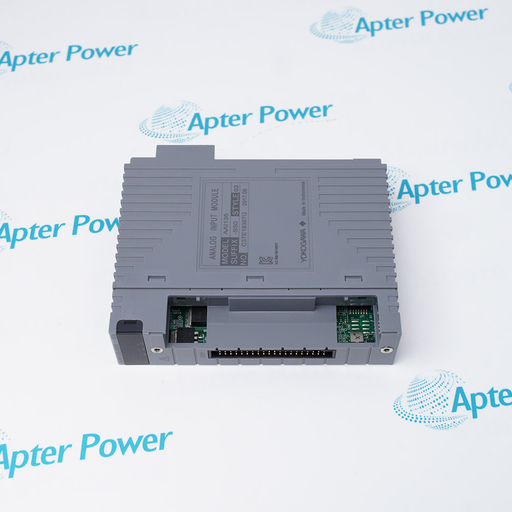
Include AAI143-S00 S1 and any revision or assembly number visible on the item. Keep the exact reference on your enquiry and quotation.
-
Check the offered item before ordering
Request available label and connector photos. Have your maintenance team compare the offered AAI143-S00 S1 with the installed equipment and applicable Yokogawa documentation.
Technical specifications for AAI143-S00 S1
-
Manufacturer:Yokogawa
-
Product Category:DCS Systems
-
Spare Part Number:AAI143-S00 S1
-
Weight:0.28 kg
-
Tariff Code:8537101190
-
I/O role:Analog input
-
Reference design:AAI143-S
-
Channels:16
-
Signal:4–20 mA
-
Allowable input:24 mA
-
Accuracy:±16 µA
-
Data update:10 ms
-
Isolation:Input-to-system isolation
-
Transmitter wiring:2-wire or 4-wire setting by channel
Information
- AAI143-S00 S1 brings isolated 4–20 mA process signals into compatible CENTUM FIO measurement channels.
Isolation: Input to system
Configuration: Per-channel transmitter wiring
The AAI143 reference specifies ±16 µA analog accuracy, a 10 ms data-update period and 24 mA allowable input. A setting pin selects a two-wire or four-wire transmitter arrangement by channel. Loop supply and the complete field wiring path must be evaluated for the selected transmitter.
AAT/AAI module positions are not interchangeable on appearance alone. Preserve the exact AAI143-S00 S1 marking, terminal assignment, transmitter settings and any configured redundant partner. Recommission each affected loop against a known current or process reference.
-
Yokogawa AAI143-S00 S1 technical reference
Apter Power technical reference - PDF, 2 pages. Product identity, verified characteristics, system role and engineering checks. -
Yokogawa AAI143-S00 S1 installation verification guide
Apter Power installation guide - PDF, 1 page. Pre-installation, configuration, commissioning and acceptance checks.
Compatibility scope: Match the S00 S1 style to the FIO node, two- or four-wire transmitter supply arrangement, terminal hardware and channel isolation design.
-
Process transmitter acquisition
Read isolated 4–20 mA signals from compatible pressure, flow, level or other process transmitters. -
Mixed transmitter wiring
Support channel-specific two-wire or four-wire connections in the approved terminal arrangement. -
Control-loop feedback
Provide measured analog values to regulatory control and alarm logic in the FIO station. -
Analog I/O restoration
Replace a matched input module while preserving channel scaling, transmitter wiring and redundancy where used.
Record and restore each two-/four-wire selection.
Check current and voltage drop at the field transmitter.
Save channel ranges and alarm configuration.
Use approved loop bypass and isolation procedures.
Verify module style, node and terminal assembly.
Compare known current and displayed value after fit.
Alternative Names
Technical notes
Technical basis: Yokogawa GS 33J60F60-01EN, Analog I/O Modules for FIO.
Applicability: AAI143-S technical figures are reference-design values. Match the complete offered style, host and terminal configuration before applying them.
Integration focus: Review each current loop as an installed circuit, including transmitter supply, isolation boundary and signal acceptance.

FAQ View All FAQ
-
How is a two-wire transmitter connected to AAI143-S00 S1?Select the documented two-wire channel setting and verify the loop supply and voltage-drop budget in the installed terminal arrangement.
-
How should a four-wire transmitter be checked on AAI143-S00 S1?Confirm the channel setting and external transmitter supply, then verify the measured loop current.
-
What should be checked when an isolated transmitter loop on AAI143-S00 S1 shows noise?Inspect the transmitter supply, field shielding, terminal wiring and loop isolation arrangement; compare the reading with a calibrated reference at the module input.
-
What could cause a 4–20 mA reading on AAI143-S00 S1 to be low?Check loop supply, transmitter output, wiring resistance, terminals, channel setting and scaling.
-
Can a Zener barrier be connected directly to AAI143-S00 S1?The AAI143 reference requires an appropriate isolation-barrier arrangement for the specified intrinsically safe use; check the approved system design.
-
What should be retained before exchanging AAI143-S00 S1?Save channel scaling, two-/four-wire settings, terminal map, alarms and redundant pairing.
-
How should analog accuracy be interpreted for AAI143-S00 S1?The ±16 µA figure is the module reference accuracy; total installed-loop error also includes transmitter, wiring and configuration.
-
What commissioning test follows installation of AAI143-S00 S1?Apply a known loop current or controlled process signal and verify the engineering-unit reading and diagnostics on every affected channel.
Supporting new and legacy automation
-
Please try to be as accurate as possible with your search.
-
We can quote you on 1000s of specialist parts, even if they are not listed on our website.
-
We can't find any results for “”.
You May Also Like
Product Browsing History
-
Whatsapp: +86 18030235313
Send us a message. -
sales13@apterpower.com
Complete our online form. -
+86 18030235313
Speak to our team in your native language.