-
Match the complete marking
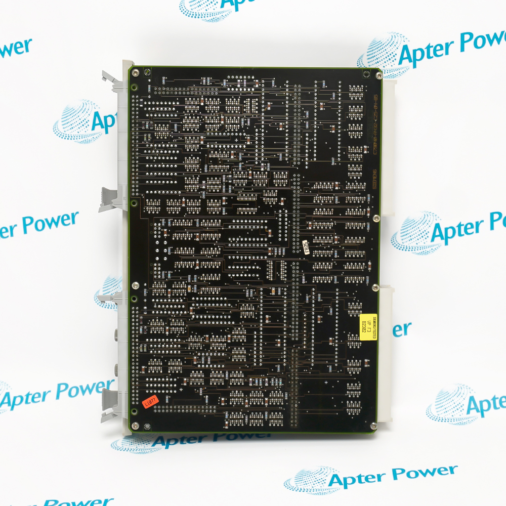
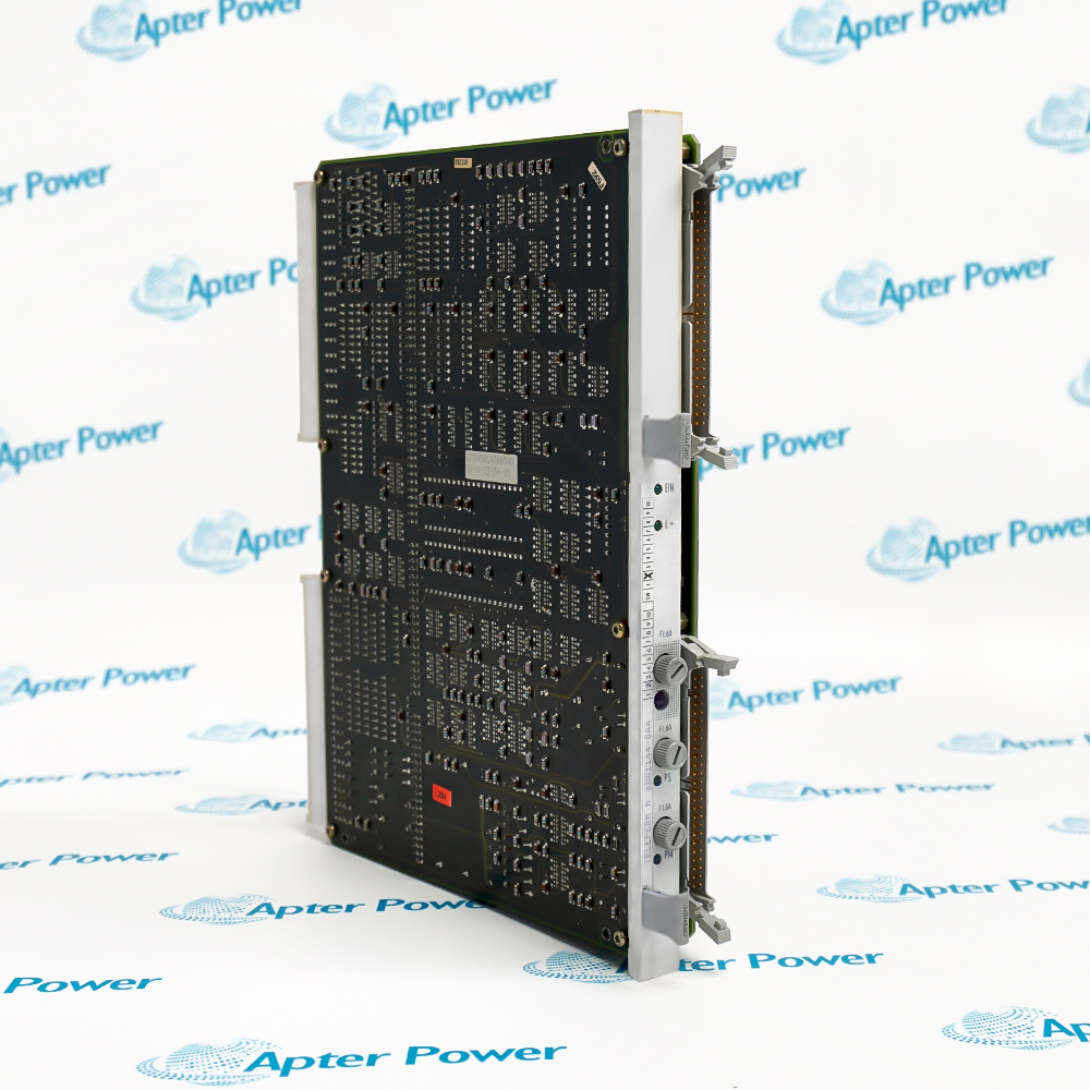
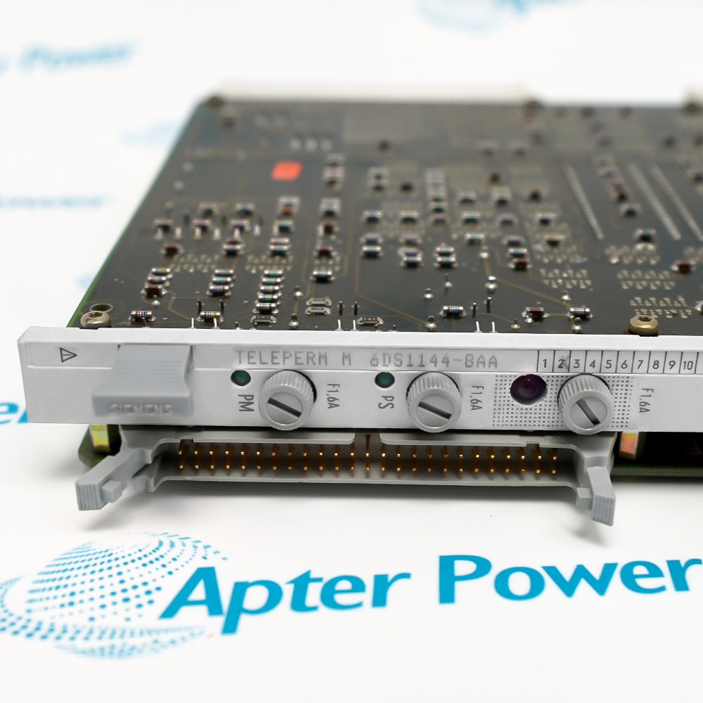
Provide the complete Siemens 6DS1144-8AA marking.
-
Check the offered item before ordering
Request available label and connector photos. Have your maintenance team compare the offered 6DS1144-8AA with the installed equipment and applicable Siemens instructions.
Technical specifications for 6DS1144-8AA
-
Manufacturer:Siemens
-
Product Category:PLC Systems
-
Spare Part Number:6DS1144-8AA
-
Weight:0.64 kg
-
Tariff Code:8537101190
-
Processor-side bus connections:2 redundant paths
-
I/O-side bus connections:1 extension bus
-
Nominal L+ supply:24 V DC
-
L+ supply range:19–33.5 V DC
-
L+ current:100 mA, plus PS/PM loads
-
Nominal bus supply:5 V DC
-
Bus supply range:4.5–5.5 V DC
-
5 V current demand:300 mA
-
Fuse ratings:3 × 1.6 A, fast acting
-
Cabinet operating temperature:0–40 °C
-
Processor-bus connectors:X3 and X4, 50-pin ribbon
-
Extension system limit:Up to 7 I/O extensions in the specified AS 235H arrangement
Information
- Siemens 6DS1144-8AA couples two redundant processor-side I/O buses to one extension bus and supervises their address, data and control behavior.
Bus supervision: Compare processor-side activity to identify inconsistent redundant behavior.
Extension integration: Cabinet addressing and separate supply domains form part of the operating arrangement.
Comparison of address, data and control activity supports identification of inconsistent processor-side behavior. The resulting diagnostics must be interpreted in the context of the active master and extension configuration.
Cabinet addressing, ribbon connections and the separate supply domains determine the installed extension arrangement. These associations remain important when an individual module is exchanged.
6DS1144-8AA Official Technical Excerpt
Siemens 6DS1144-8AA: original manufacturer technical information covering the specified interfaces and operating limits. PDF · 8 pages.6DS1144-8AA Installation & Verification Guide
Apter Power guide covering redundant buses, supply diagnosis, rack connections, master-path checks, extension acceptance. PDF · 5 pages.
Application boundary: System extension capacity describes the cabinet arrangement, not a field-channel count provided by this module.
Redundant processor coupling
Two processor-side bus paths feed the EAVU in an AS 235H arrangement.I/O extension selection
The active master is connected to the designated extension-side I/O bus.Bus discrepancy supervision
Address, data and control comparison supports diagnosis of inconsistent redundant behavior.Addressed I/O extension cabinets
Cabinet addressing and backplane configuration define the extension served by the redundant processor paths.
Follow the AS 235H procedure for the affected I/O extension and process. Identify the active master and the consequences of losing this extension before isolating supplies or disturbing ribbon connections.
Verify L+ within 19–33.5 V and the bus supply within 4.5–5.5 V using the correct references. A valid 24 V reading alone does not establish that the 5 V bus circuitry is operating.
Keep the existing extension address and backplane configuration associated with the correct rack. Do not transfer a module into a different extension and assume the retained cabinet settings are suitable without checking the system design.
After controlled restoration, check which processor path controls the I/O bus and whether the corresponding status agrees with the intended master. A supply LED alone is not evidence of correct bus selection.
Record the restored bus routing, supply checks and redundancy-test results. Retain any fault history that distinguishes supply loss, ribbon connection problems and comparator conditions before returning the extension to normal service.
Carry out the approved AS 235H switchover and diagnostic tests for this extension. Confirm that process I/O remains consistent with the designed response and that comparator or grouped-error indications are resolved.
Alternative Names
Technical notes
Operating boundary: The module's redundant and nonredundant bus sides have different roles.
Integration details: Preserve X3/X4 assignment, cabinet jumpers and fuse positions during service.

FAQ View All FAQ
-
Why can 6DS1144-8AA show a valid 24 V supply while the I/O extension remains unavailable?The interface also depends on its separate bus supply. Check each supply domain with the correct reference before attributing the fault to a processor or ribbon cable.
-
How should X3 and X4 be traced during 6DS1144-8AA replacement?Retain their association with the two processor paths. Crossing these connections can make the observed master selection inconsistent with the intended redundant configuration.
-
What does a successful power-up fail to prove about 6DS1144-8AA redundancy?It does not demonstrate master selection or continued I/O behavior during a switchover. Validate the approved redundant operating sequence and review comparator indications.
-
Why must cabinet address settings be checked when moving 6DS1144-8AA?The extension assignment belongs to the installed cabinet arrangement. A module moved without checking the address and backplane setup can connect the wrong I/O extension.
-
How can a bus discrepancy indication on 6DS1144-8AA be investigated logically?Compare the two processor paths, ribbon routing and address/data/control behavior before replacing unrelated I/O. Distinguish a comparator condition from loss of a supply domain.
-
Can a failed fuse on 6DS1144-8AA be bypassed to restore the extension?No. Establish the cause in the affected supply or load path and restore the specified protective arrangement. A bypass defeats the intended protection and does not resolve the underlying fault.
-
Why is the maximum extension count for 6DS1144-8AA not an I/O channel count?It describes system expansion positions. Actual field-channel capacity depends on the I/O modules and configured extension arrangement, which must be assessed separately.
-
What should be observed after an approved master switchover involving 6DS1144-8AA?Confirm the selected processor path, consistent process I/O and resolved diagnostic indications. Preserve the test result so a later power or bus fault can be distinguished from a configuration issue.
Supporting new and legacy automation
-
Please try to be as accurate as possible with your search.
-
We can quote you on 1000s of specialist parts, even if they are not listed on our website.
-
We can't find any results for “”.
Related cases and sourcing guidance
View all case studiesYou May Also Like
Product Browsing History
-
Whatsapp: +86 18030235313
Send us a message. -
sales13@apterpower.com
Complete our online form. -
+86 18030235313
Speak to our team in your native language.