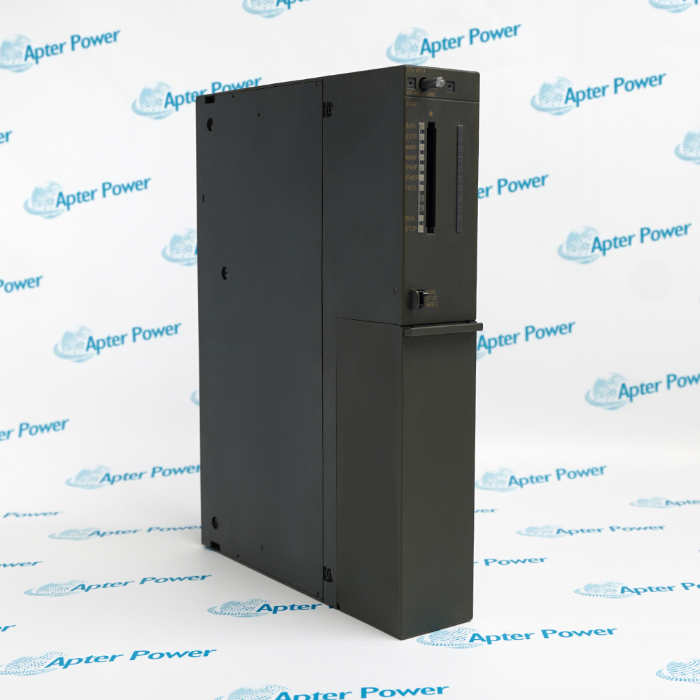
Product image is representative; revision or series may vary. Contact us to request a specific version.
Product Describe:
Siemens 6ES7431-7KF10-0AB0 is an SM 431 eight-channel RTD analog input module with 16-bit resolution. It supports parameterizable Pt and Ni resistance-temperature measurements with diagnostics and hardware-interrupt capability.
Siemens 6ES7431-7KF10-0AB0 acquires eight differential resistance-temperature channels for an S7-400 station while keeping sensor linearization, channel diagnostics and process-interrupt behavior within the module configuration.
Eight differential RTD input channels.
Pt and Ni sensor linearization with 16-bit conversion.
25 ms update rate for all eight channels.
Readable diagnostics and configurable hardware interrupts.
The retained STEP 7 configuration links each channel to its sensor characteristic, wiring method, diagnostic behavior and process-limit response.
Important Notice: Match every RTD type, three- or four-wire circuit and channel range before the module is returned to service.
The official excerpt covers the exact SM 431 RTD module data and commissioning pages; the field guide organizes the model-specific wiring, setup, diagnostic and acceptance checks.

Multi-point RTD acquisition
Collects eight Pt or Ni resistance-temperature inputs in one S7-400 slot.
Temperature monitoring
Supports channel-specific measurement configuration and diagnostic evaluation.
Process-limit supervision
Uses configured hardware interrupts for applications that require close monitoring.
Legacy S7-400 maintenance
Restores the recorded SM 431 position while preserving terminal and parameter assignments.
Apply these checks to the exact Siemens 6ES7431-7KF10-0AB0 RTD input position before returning its temperature channels to service.
1
Confirm the complete 6ES7431-7KF10-0AB0 order number and the recorded S7-400 slot.
2
Place the controller and connected temperature circuits in the approved maintenance state.
3
Record every RTD type, three- or four-wire connection and channel assignment before removal.
4
Verify shield routing and keep each field cable within the documented 200 m limit.
5
Restore the 48-pin connector without changing channel polarity or common connections.
6
Load the retained STEP 7 parameter set and compare measuring method and sensor range by channel.
7
Review INTF/EXTF indications and read the module diagnostic record after energization.
8
Functionally compare all eight temperature values and configured interrupt limits before release.
Technical notes
Match 6ES7431-7KF10-0AB0 to the recorded S7-400 slot, 48-pin connector and STEP 7 channel parameters. Preserve every RTD wiring method and release the module only after all eight values, diagnostics and configured interrupts are verified.