Speak to a sourcing specialist
sales13@apterpower.com

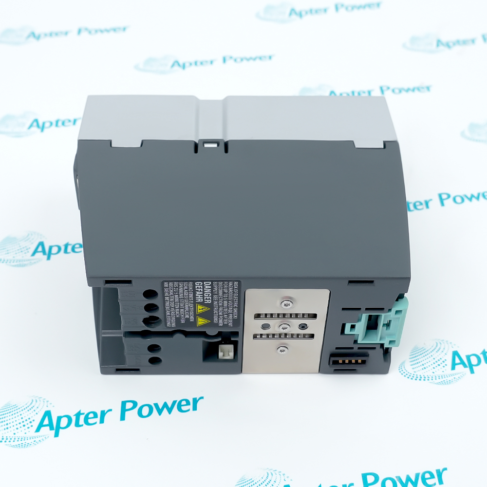
6SL3320-1TE33-1AA3

Chassis Single Motor Module
Product image is representative; revision or series may vary. Contact us to request a specific version.

Product Describe:

Siemens 6SL3320-1TE33-1AA3 is an internally air-cooled SINAMICS S120 chassis power stage that converts shared DC-link energy into a controlled three-phase motor supply. A connected Control Unit provides the drive-control functions through DRIVE-CLiQ.
  • Manufacturer part number
    6SL3320-1TE33-1AA3
  • Shipping
    Swift global dispatch
  • Condition
    New, original product
  • Shipping size (est.)
    5cm x 27cm x 41.2cm
  • Country of Origin
    USA
Get a quick price for 6SL3320-1TE33-1AA3
E-mail *
Mobile *
Company
Content *
Quantity *
Upload (gif, jpg, jpeg, png, bmp, doc, docx, xls, xlsx, ppt, pdf, csv)
For more information on how your data is processed and stored by Apterpower please read our privacy policy

What happens after you enquire

  • 0

    Review your reference

    Send the complete 6SL3320-1TE33-1AA3 reference, nameplate photos and the required motor duty.

  • 1

    Confirm the offer

    Review the offered power-stage state, cooling arrangement, connectors and included drive options.

  • 2

    Arrange dispatch

    Confirm quantity, delivery details and the agreed dispatch date before shipment arrangement.

  • Match the complete marking

    Include the complete 6SL3320-1TE33-1AA3 reference, hardware state, motor duty and installed Line Module / Control Unit arrangement.

  • Check the offered item before ordering

    Request nameplate, power-terminal and fan-transformer photographs. Compare the offered 6SL3320-1TE33-1AA3 with the retained drive configuration and applicable GX chassis instructions.

Technical specifications for 6SL3320-1TE33-1AA3

  • Manufacturer:
    Siemens
  • Product Category:
    PLC Systems
  • Spare Part Number:
    6SL3320-1TE33-1AA3
  • Weight:
    5.1 kg
  • Tariff Code:
    8537101190
  • Drive topology:
    Single Motor Module; shared DC-link input
  • Rated output current:
    310 A
  • Low-overload base current IL:
    302 A
  • High-overload base current IH:
    277 A
  • S6 intermittent current:
    340 A at 40% duty
  • Maximum output current:
    453 A; duty limits apply
  • Low-overload power reference:
    160 kW at 400 V / 50 Hz
  • High-overload power reference:
    132 kW at 400 V / 50 Hz
  • Low / high-overload power at 460 V:
    250 / 200 hp, 60 Hz
  • DC-link range, GH3 technical table:
    510–750 V DC, including stated overshoot
  • Motor-output voltage:
    0 to 0.72 × DC-link voltage, three-phase AC
  • Electronics supply:
    24 V DC; 20.4–28.8 V
  • Electronics current, exact-model table:
    0.9 A
  • Rated DC input, Basic/Smart Line Module:
    372 A
  • Rated DC input, Active Line Module:
    335 A
  • Low-overload DC input, Basic/Smart / Active:
    362 / 326 A
  • High-overload DC input, Basic/Smart / Active:
    331 / 298 A
  • Rated pulse frequency:
    2 kHz
  • Maximum pulse frequency:
    8 kHz with derating
  • DC-link capacitance:
    6300 µF
  • Fan supply reference:
    2 AC 400 V; transformer tap matched to feeder
  • Fan current at 50 / 60 Hz:
    1.8 / 2.7 A
  • Power loss at 400 V / 50 Hz:
    2.96 kW, rated-duty reference
  • Power loss at 460 V / 60 Hz:
    3.1 kW, rated-duty reference
  • Cooling-air demand:
    0.36 m³/s
  • Un-derated / derated ambient ceiling:
    40 / 55 °C
  • Motor cable length, shielded / unshielded:
    300 / 450 m maximum
  • DC-link / motor / PE connection:
    M10; 25 N·m with specified cable lugs
  • Power connection capacity:
    2 × 240 mm² maximum
  • Temperature-sensor inputs:
    KTY84-1C130 / PTC / PT100
  • DRIVE-CLiQ connections:
    X400, X401, X402
  • Enclosure protection:
    IP20; GX frame

Information

Overview Downloads Applications / Compatibility Product Precautions
  • Siemens 6SL3320-1TE33-1AA3 supports coordinated motor operation within a common-bus drive installation. Its selection depends on the load cycle, cooling path and companion drive equipment, while commissioning must reconcile power connections, thermal feedback and the retained control configuration.
Shared-bus operation: Energy returned by one axis can be used by another motoring axis within the coordinated DC-link system.
Duty-based selection: Continuous, high-overload and intermittent requirements must be assessed as different load cases.
System diagnostics: Power-stage status and temperature feedback are evaluated with the Control Unit and installed drive functions.
The Motor Module takes power from the DC link rather than directly from a three-phase AC feeder. A Line Module supplies the common bus, and a CU320-2 or suitable SIMOTION D controller executes the drive functions through DRIVE-CLiQ. Both synchronous and induction motors can be operated when the motor data, feedback and control mode are correctly configured; the power stage alone does not establish a complete drive.

The GX assembly uses internal forced-air cooling and a fan transformer whose tapping must match the actual fan-supply voltage. Incorrect tapping can reduce cooling or operate the fan fuses even when the electronics appear ready. Cabinet airflow, ambient temperature, switching frequency and the selected overload duty therefore belong to the same thermal assessment.

The control interface separates motor-temperature sensing, pulse-enable functions, auxiliary supply and brake-adapter connections. Sensor insulation and polarity must suit the connected motor circuit, while Safety Integrated functions require the appropriate configuration and acceptance. An extinguished DC-link indicator is not evidence that stored energy has dissipated; isolation and voltage verification remain separate from ordinary status checks.
Controller platform reference: Siemens SINAMICS S120 chassis drive system. Coordinate the shared DC link, Control Unit and configured motor protection.
The 6SL3320-1TE33-1AA3 files separate original chassis hardware information from a drive-restoration workbook. View PDF provides an engineering dossier focused on duty selection, shared-bus operation and installation boundaries.
Original manufacturer pages retain their technical context. Use the Apter Power guide with the applicable manufacturer instructions and approved installation design.
System and supply context: The GX Motor Module operates within a coordinated SINAMICS S120 chassis system. The Line Module, Control Unit, feedback equipment, braking arrangements and filters are separate selection items and are included only when itemized.

Application scope: Apply the unit to a motor duty supported by its current/time capability and the installed cooling conditions. The motor-power references depend on the stated voltage and overload basis; they do not replace a load-cycle calculation.
Prepare Siemens 6SL3320-1TE33-1AA3 for its configured installation using these checks.
Verify discharge after isolation

Isolate all supplies, wait at least five minutes and measure DCP-to-DCN voltage before work; LEDs do not prove absence of hazardous voltage.

Retain the correct fan tapping

Check the actual supply and -T10 tapping before operation, including the installed fan fuses and airflow path.

Distinguish power and auxiliary connections

Keep the DC bus, motor output, protective earth and electronics supply on their designated terminals.

Protect temperature feedback integrity

Use suitably isolated sensors, shield their leads and retain KTY polarity; use the appropriate external sensor module where safe separation is unavailable.

Review pulse frequency and load duty

Apply current derating and the required recovery intervals instead of combining incompatible peak ratings.

Validate configured safety and braking

Confirm enabled functions and brake-adapter wiring through the approved acceptance procedure before production release.

Alternative Names

Siemens 6SL3320-1TE33-1AA3 6SL3320 1TE33 1AA3

Technical notes

Fan-supply routing: On GX hardware the fan supply connects directly to fuse holders -F10 and -F11. The X9 L1/L2 fan connection shown for larger HX/JX frames must not be transferred to GX.

Auxiliary output boundary: X42 supports designated Control Unit, Sensor Module and Terminal Module loads. It is not a general-purpose 24 V cabinet distribution source.

Stored-energy indication: DC LINK and POWER OK indications describe component state, not a verified isolation condition. Check all supply paths and measure the bus after the prescribed discharge interval.

Load-basis comparison: Input-current and motor-power values change with Line Module type and overload duty. Keep those qualifiers attached when sizing the shared supply and motor branch.


FAQ View All FAQ

  • Why can the fan fuses of 6SL3320-1TE33-1AA3 operate even when the drive-control electronics start normally?
    The fan transformer is a separate supply path. Compare the actual feeder with the selected -T10 tap and inspect the fan circuit; incorrect tapping can cause fuse operation or inadequate cooling without preventing electronics startup.
  • Can a dark DC LINK indicator on 6SL3320-1TE33-1AA3 be used as the release condition for maintenance?
    No. Hazardous voltage may remain irrespective of that LED. Isolate every supply, wait at least five minutes and measure the DC-link voltage before work; the isolation procedure must also account for other modules connected to the shared bus.
  • Why must the motor power assigned to 6SL3320-1TE33-1AA3 be checked against the overload basis?
    The low-overload and high-overload references reserve different current capacity for the duty cycle. Compare the actual torque/current profile and recovery periods rather than choosing the higher power figure independently of the application.
  • Does the shared DC link of 6SL3320-1TE33-1AA3 automatically guarantee that regenerated energy can always be absorbed?
    No. Other motoring axes can use returned energy, but that demand may disappear. Check the selected Line Module, braking arrangement and complete energy balance for the actual operating sequence.
  • May the X42 supply on 6SL3320-1TE33-1AA3 power arbitrary external cabinet loads?
    No. It supports the designated drive-control and interface components. Additional cabinet loads can overload the control-interface supply; provide a separately assessed distribution circuit instead of treating this connector as a spare power outlet.
  • What could prevent a connected KTY sensor from protecting the motor through 6SL3320-1TE33-1AA3?
    Incorrect sensor polarity, shielding, isolation or configuration can invalidate temperature supervision. Check the selected sensor type and signal response under the approved procedure; a connected lead alone does not demonstrate working overtemperature protection.
  • Why does increasing the pulse frequency of 6SL3320-1TE33-1AA3 require a new current assessment?
    Higher switching frequency raises power-stage losses and reduces available output current. Apply the appropriate derating and reassess cabinet heat removal rather than retaining the full base-frequency current rating.
  • Can the EP terminals of 6SL3320-1TE33-1AA3 be assumed to provide pulse inhibition without a configuration check?
    No. Their pulse-inhibit function depends on enabled Safety Integrated Basic Functions. Confirm the actual safety configuration, wiring and acceptance results; a terminal connection by itself does not establish a validated safety function.
Manufacturers

Product Browsing History

Revisit the products you recently viewed on Apter Power.
SPEAK TO OUR TEAM
Let’s find the right solution for you.
Send us the part number, quantity and delivery destination. Our team will help confirm availability and lead time.
  • Whatsapp: +86 18030235313

    Send us a message.
  • sales13@apterpower.com

    Complete our online form.
  • +86 18030235313

    Speak to our team in your native language.