-
Match the complete marking
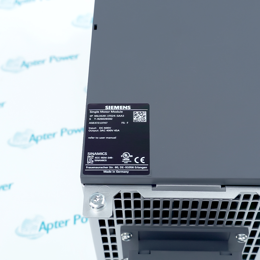
Include 6SL3120-1TE24-5AA3 and every visible hardware revision or assembly label in the enquiry; keep the exact order reference on the quotation.
-
Check the offered item before ordering
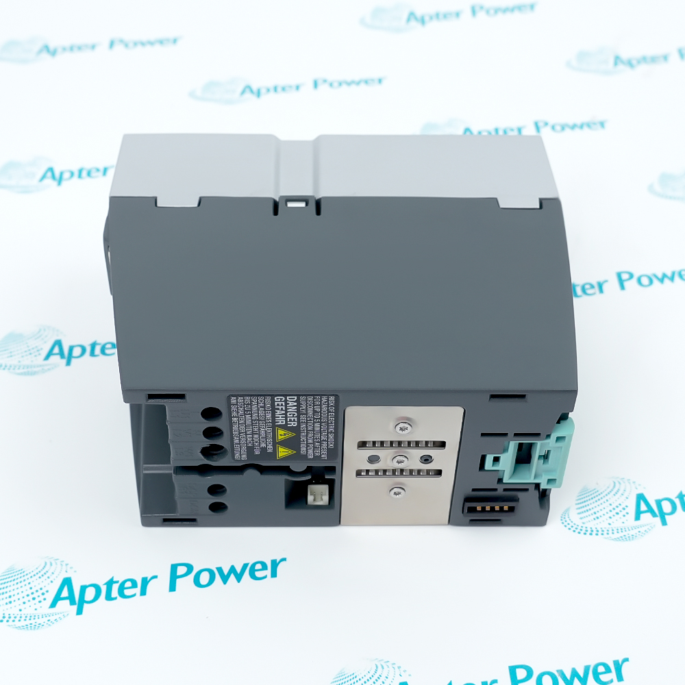
Request label and connector photos. Have maintenance compare the offered reference with the installed motor module and Siemens line-up drawings before ordering.
Technical specifications for 6SL3120-1TE24-5AA3
-
Manufacturer:Siemens
-
Product Category:Servo Drives
-
Spare Part Number:6SL3120-1TE24-5AA3
-
Weight:9.42 kg
-
Tariff Code:8537101190
-
Drive family:SINAMICS S120
-
Module arrangement:Single Motor Module, booksize
-
Cooling:Internal air cooling
-
DC-link range:510-720 V DC
-
Motor output:Three-phase; U2/V2/W2
-
Rated output current:45 A
-
Base-load current IH:38 A
-
S6 current, 40% duty:60 A
-
Maximum current:85 A
-
Rated pulse frequency:4 kHz
-
Rated power at 600 V DC:24 kW for typical standard asynchronous motor
-
DC-link current:54 A, rated
-
DC-link busbar capacity:200 A
-
24 V busbar capacity:20 A
-
24 V electronics demand:1.2 A maximum
-
DC-link capacitance:1,175 uF
-
Power loss, maximum:460 W at rated power, internal cooling
-
Cooling-air requirement:0.031 m3/s
-
Sound pressure at 1 m:Below 65 dB
-
Degree of protection:IP20
-
Motor terminal:M6 screw studs, X1
-
Protective earth:M6 screw
-
Motor brake connector:X11; 24 V DC, 2 A
-
Motor cable length, shielded:100 m maximum, published condition
-
Motor cable length, unshielded:150 m maximum, published condition
Information
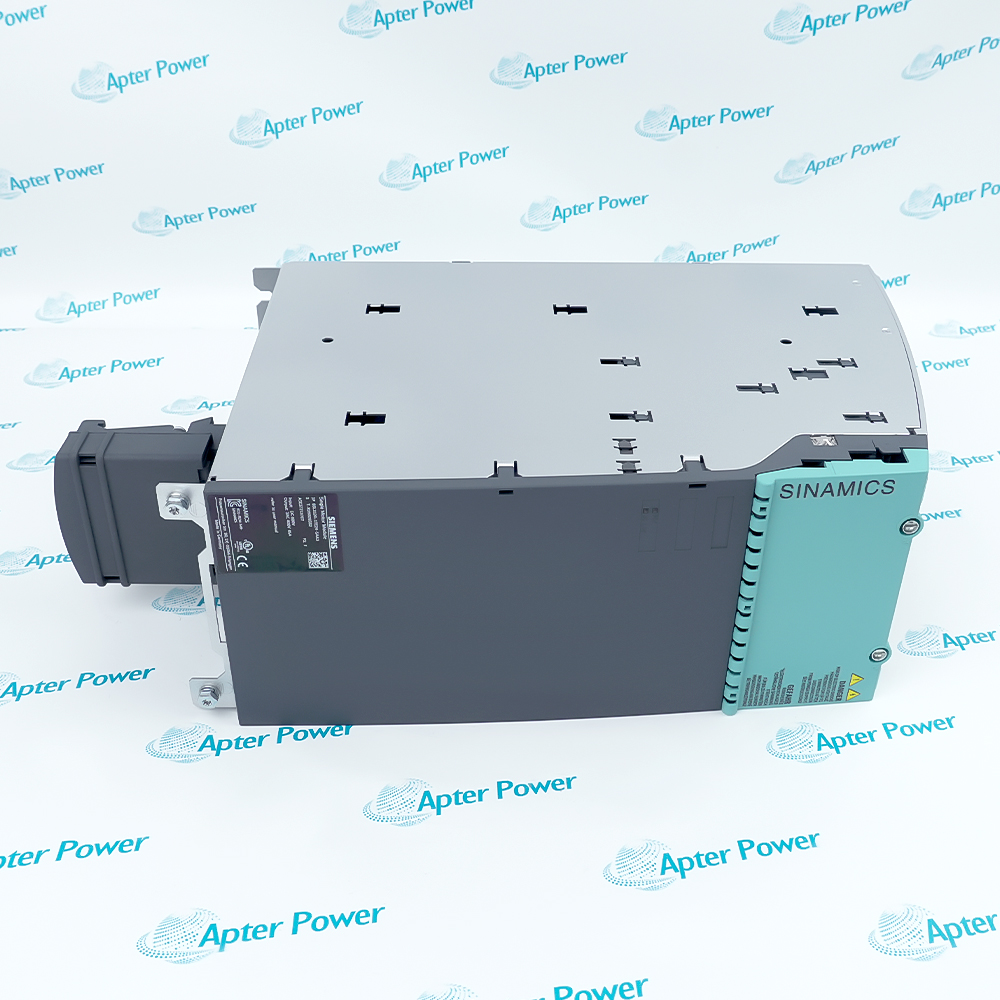
- Siemens 6SL3120-1TE24-5AA3 is a 45 A SINAMICS S120 booksize Single Motor Module. It draws from the common DC link and supplies a controlled three-phase output to one motor axis.
Rated output current: 45 A; base-load current 38 A
Cooling: Internal air; booksize construction
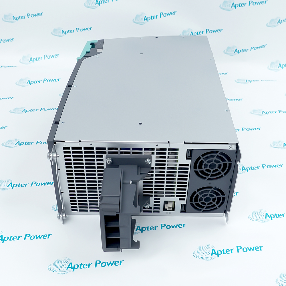
The motor connection uses X1 U2/V2/W2 with M6 screw studs and a separate M6 protective-earth point. X11 supplies a 24 V DC, 2 A motor-brake interface. Check terminal hardware, conductor sizing, brake wiring and the machine safety sequence against the approved cabinet drawing.
Internal air cooling requires an unobstructed flow path. The published maximum power loss is 460 W and cooling-air demand is 0.031 m3/s; cabinet thermal assessment must account for the actual load and ambient conditions. The IP20 module also depends on the enclosure for touch protection and environmental shielding.
-
Siemens 6SL3120-1TE24-5AA3 technical reference
Original Siemens NC82 catalog excerpt - PDF, 2 pages. Exact 45 A order entry and related operating data. -
6SL3120-1TE24-5AA3 engineering technical data
Single Motor Module output ratings, DC-link, cooling and integration boundaries. Apter Power PDF, 1 page.
Application boundary: The applications below describe system integration roles. Match the exact module marking, control version and machine design before substitution.
-
Single-axis motor drive
Use within a documented S120 cabinet where one motor axis is assigned to a 45 A Single Motor Module. Verify motor and drive data before enabling the axis. -
Shared DC-link assembly
Coordinate the module with the S120 line module and common DC-link busbars. Check 24 V electronics supply and permitted busbar loading in the whole lineup. -
Motor-brake integration
Use the X11 brake circuit only after matching the 24 V, 2 A interface and the brake coil, suppression and machine safety sequence. -
Service replacement
Keep full order code, axis project, safety settings and motor wiring together. Commission the replacement with controlled low-risk motion and fault-log review.
Follow Siemens and site lockout procedures; verify discharge at the specified points before touching power terminals.
Confirm DC-link voltage, busbar ratings and 24 V electronics supply for the existing S120 cabinet.
Inspect fan operation, flow paths and ambient conditions before applying load; do not obstruct the internally cooled module.
Verify U2/V2/W2, PE and X11 brake connections against the approved drawings and motor data.
Check shield termination, grounding and cable length; published maxima depend on the selected motor-cable system.
Restore the approved parameter and safety project, then test axis direction, feedback, braking and fault behavior before production release.
Alternative Names
Technical notes
Drive integration: Confirm the 45 A Single Motor Module arrangement, DC-link supply, motor connection and cooling against the approved S120 cabinet design.
Acceptance: Preserve the axis project, safety configuration and motor data before replacement; verify PE, shield and fan operation before controlled start.
Technical reference: Siemens NC 82 SINAMICS S120 catalogue (2017), booksize Single Motor Modules; Siemens exact-order data sheet.

FAQ View All FAQ
-
How should 6SL3120-1TE24-5AA3 be assessed before replacing a Motor Module in an S120 lineup?Compare the complete order number, module topology, DC-link arrangement, control wiring and installed firmware/safety configuration. Confirm the replacement is approved for the existing Control Unit and machine project before energizing.
-
What can cause 6SL3120-1TE24-5AA3 to trip during acceleration even when the continuous current rating appears sufficient?Compare the drive trace with the base-load, S6 and peak-current limits under the actual duty cycle. Check motor load, current limits, ramp settings and cooling before attributing a trip to the module.
-
How should cabinet cooling be checked for 6SL3120-1TE24-5AA3 at rated load?Use the manufacturer maximum power-loss and air-flow values to review the cabinet thermal design. Inspect fan operation, unobstructed inlet and outlet paths, and ambient temperature with the drive operating at representative load.
-
Why should motor cable length be reviewed when integrating 6SL3120-1TE24-5AA3?The published 100 m shielded and 150 m unshielded maxima are conditional. Compare actual cable type, length, motor insulation and EMC installation; determine whether reactors or filters are required by the applicable Siemens system guide.
-
How should a technician verify the DC-link supply before commissioning 6SL3120-1TE24-5AA3?Confirm the system is isolated for wiring work, then follow the S120 startup procedure to check the DC-link range and 24 V electronics supply at the specified test points. Do not treat a nominal 600 V label as permission to bypass discharge checks.
-
When is a 24 V motor-brake circuit compatible with 6SL3120-1TE24-5AA3?Check the X11 brake connection against the documented 24 V DC, 2 A interface and the motor brake coil, suppression and timing requirements. Verify the machine safety sequence before releasing the axis.
-
How can grounding faults affect 6SL3120-1TE24-5AA3 after a replacement?Inspect the M6 protective-earth connection and shield termination. Compare the new wiring with the approved cabinet drawing and test the drive under representative motor current for EMC or earth-fault symptoms.
-
What acceptance evidence should be retained after 6SL3120-1TE24-5AA3 is exchanged?Record the original and replacement complete markings, wiring and PE checks, DC-link and 24 V readings, cooling condition, safety configuration and a controlled axis test with fault history.
Supporting new and legacy automation
-
Please try to be as accurate as possible with your search.
-
We can quote you on 1000s of specialist parts, even if they are not listed on our website.
-
We can't find any results for “”.
Related cases and sourcing guidance
View all case studiesYou May Also Like
Product Browsing History
-
Whatsapp: +86 18030235313
Send us a message. -
sales13@apterpower.com
Complete our online form. -
+86 18030235313
Speak to our team in your native language.