-
Match the complete marking
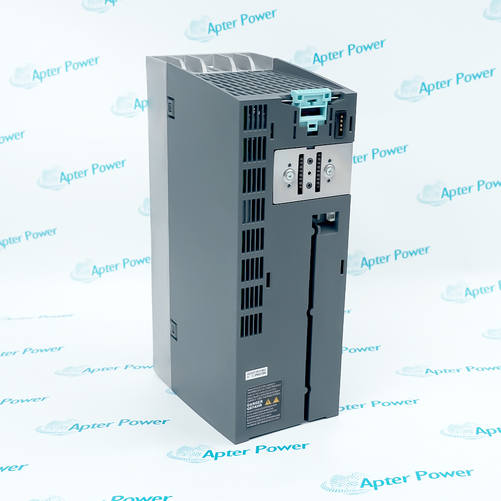
Include the complete 6SL3040-1MA00-0AA0 reference, installed firmware and PROFIBUS/DRIVE-CLiQ arrangement.
-
Check the offered item before ordering
Request label and connector photographs. Have your maintenance team compare the offered 6SL3040-1MA00-0AA0 with the installed drive project and applicable Siemens CU320-2 DP instructions.
Technical specifications for 6SL3040-1MA00-0AA0
-
Manufacturer:Siemens
-
Product Category:PLC Systems
-
Spare Part Number:6SL3040-1MA00-0AA0
-
Weight:2.22 kg
-
Tariff Code:8537101190
-
Independent digital inputs:12, isolated in reference groups
-
Bidirectional digital I/O:8, non-isolated
-
DRIVE-CLiQ ports:4, X100–X103
-
PROFIBUS interface:1, X126, 9-pin Sub-D
-
Local service LAN:1, X127; 10/100 Mbit link
-
Serial interface:1, X140, RS232 with USS support
-
Option slots:1
-
Electronics input:24 V DC; 20.4–28.8 V
-
Electronics current:1.0 A maximum, excluding DRIVE-CLiQ and digital outputs
-
Total input current:6.5 A maximum including connected outputs
-
Power loss:24 W maximum
-
Combined output-current limit:5.5 A
-
Supply connector loop-through:20 A maximum; 15 A under UL/CSA
-
Input high threshold:15–30 V DC, including ripple
-
Input low threshold:−3 to +5 V DC, including ripple
-
Input current:3.5 mA typical at 24 V DC
-
Ordinary input delay:50 µs rising / 150 µs falling, typical
-
Fast input delay:5 µs rising / 50 µs falling, typical
-
Output current per point:0.5 A maximum
-
Output current per terminal group:2 A maximum across four outputs
-
Output high voltage:Greater than X124 supply minus 2 V under load
-
Output off-state leakage:Below 0.5 mA
-
Output switching frequency:100 Hz resistive / 0.5 Hz inductive / 10 Hz lamp maximum
-
Lamp load:5 W maximum
-
Digital I/O cable length:30 m maximum
-
DRIVE-CLiQ cable length:100 m maximum
-
PROFIBUS addresses:1–126 valid; unique per bus
-
Teleservice supply load:150 mA maximum
-
Measurement outputs:3; 0–5 V, 8-bit resolution
-
Measurement load current:3 mA maximum
Information
- Siemens 6SL3040-1MA00-0AA0 coordinates the drive components while keeping control-network communication, local service access and field I/O as distinct functions. Correct terminal references and retained configuration are essential when integrating or replacing the unit.
Network-role discipline: PROFIBUS carries the configured drive-control exchange while the LAN port serves local commissioning and diagnostics.
Retained drive identity: Firmware, parameter data and licenses on the memory card form part of the replacement configuration.
The independent digital-input groups use M1 or M2 as their reference potentials. Joining either reference to electronics ground allows a shared supply reference but removes that group’s electrical isolation. The bidirectional terminals already share electronics ground and must be assigned individually as inputs or outputs; their faster input behavior is distinct from the ordinary digital inputs.
The PROFIBUS address can be selected by rotary switches or by parameter when the switches select parameter-based addressing. A changed address takes effect after POWER ON. The LAN interface is intended for local service access, while operating-state LEDs distinguish readiness, cyclic communication and option-board conditions. A ready indication therefore does not by itself demonstrate correct setpoint exchange or licensed operation.
6SL3040-1MA00-0AA0 Official CU320-2 DP Hardware Excerpt
Original English Siemens CU320-2 DP hardware data, terminal interfaces, addressing and memory-card handling. PDF · 10 pages.6SL3040-1MA00-0AA0 Installation & Verification Guide
Apter Power drive-control workbook covering project retention, I/O reference potentials, PROFIBUS addressing, service access and acceptance. PDF · 5 pages.
Application scope: Use the integrated PROFIBUS interface for the intended controller-to-drive exchange. X127 provides local commissioning and diagnostic access; the presence of an Ethernet socket does not make this hardware the CU320-2 PN variant.
Coordinated S120 drive groups
Implement configured control functions for compatible Line Modules and Motor Modules within the retained drive topology.PROFIBUS motion-control networks
Connect the drive to a compatible master with coordinated telegrams, unique addressing and suitable bus termination.Fast external event acquisition
Use the configured fast input terminals for probe or external zero-mark signals, with suitable shielding and evaluation.Local drive-service access
Keep X127 accessible for authorized commissioning and diagnostics within the permitted local networking arrangement.
Back up the approved project and record firmware and license scope before removing hardware.
Preserve the intended isolation or shared-ground arrangement; do not add reference jumpers without reviewing their effect.
Respect per-output, four-output-group and total load limits; include connected DRIVE-CLiQ consumption.
Record switch settings, parameter addressing and termination, then verify the address after controlled power-up.
Follow ESD precautions and never withdraw or insert the card during operation.
Do not connect CAN wiring to X126, and preserve the restricted local-use arrangement at X127.
Alternative Names
Technical notes
Terminal-reference consequence: An M1-to-M or M2-to-M jumper removes the corresponding digital-input isolation. Open inputs read low; an unconnected reference can prevent intended input operation.
Supply interruption: Digital outputs deactivate during a brief interruption of the 24 V supply. Evaluate the controlled process response rather than assuming the previous output state is held.
Address activation: Switch values 0 or 127 select parameter p0918. Valid network addresses are 1–126, and changes require POWER ON before becoming effective.
Diagnostic separation: RDY and COM indications answer different questions. Check actual setpoint transfer, telegram configuration and option-board state before releasing drive operation.

FAQ View All FAQ
-
Why can a valid sensor voltage fail to operate an input on 6SL3040-1MA00-0AA0?The input also requires the correct group reference at M1 or M2. Trace the return path as well as the signal conductor. Adding a jumper to M can restore a shared reference but removes isolation and must agree with the approved circuit design.
-
Does connecting a laptop to the LAN socket of 6SL3040-1MA00-0AA0 make it a PROFINET drive controller?No. X127 is intended for local commissioning and diagnostics. Preserve its local-access restrictions and assess the installed communication option separately; do not substitute the PN variant’s interface behavior.
-
Why does a changed rotary address on 6SL3040-1MA00-0AA0 not immediately change the PROFIBUS node?Address changes become effective after POWER ON. Record the switch values, verify whether switches or p0918 own the address, and confirm a unique valid node address after the approved restart.
-
Can a 0.5 A load on every output of 6SL3040-1MA00-0AA0 be approved from the individual rating alone?No. Check the four-output group limits and the combined current allocation including DRIVE-CLiQ loads. Also apply the load-type switching-frequency limits and inspect supply drop at the actual terminals.
-
What can a steady RDY indication with incomplete COM activity mean on 6SL3040-1MA00-0AA0?The control unit may be ready while full cyclic exchange is not established. Check master telegram and parameter configuration, transferred setpoints and isochronous global-control conditions before diagnosing a failed drive component.
-
Why might a direct service cable fail to establish a link with 6SL3040-1MA00-0AA0?X127 does not support auto-MDI(X). If the other endpoint also lacks that function, use the required crossover arrangement. Check the link indication and cable before changing the retained drive configuration.
-
Does a brief 24 V interruption leave the digital outputs of 6SL3040-1MA00-0AA0 unchanged?No. The outputs deactivate during the interruption. Test the permitted control-system recovery and resulting drive command sequence under an approved procedure before relying on automatic continuation.
-
Should the memory card stay in 6SL3040-1MA00-0AA0 when a faulty control unit is returned?Retain the card securely for the replacement, because it carries firmware, parameters and licenses. Remove it only with the unit without voltage and with ESD precautions; reconcile the retained card with the replacement hardware before starting.
Supporting new and legacy automation
-
Please try to be as accurate as possible with your search.
-
We can quote you on 1000s of specialist parts, even if they are not listed on our website.
-
We can't find any results for “”.
Related cases and sourcing guidance
View all case studiesYou May Also Like
Product Browsing History
-
Whatsapp: +86 18030235313
Send us a message. -
sales13@apterpower.com
Complete our online form. -
+86 18030235313
Speak to our team in your native language.