-
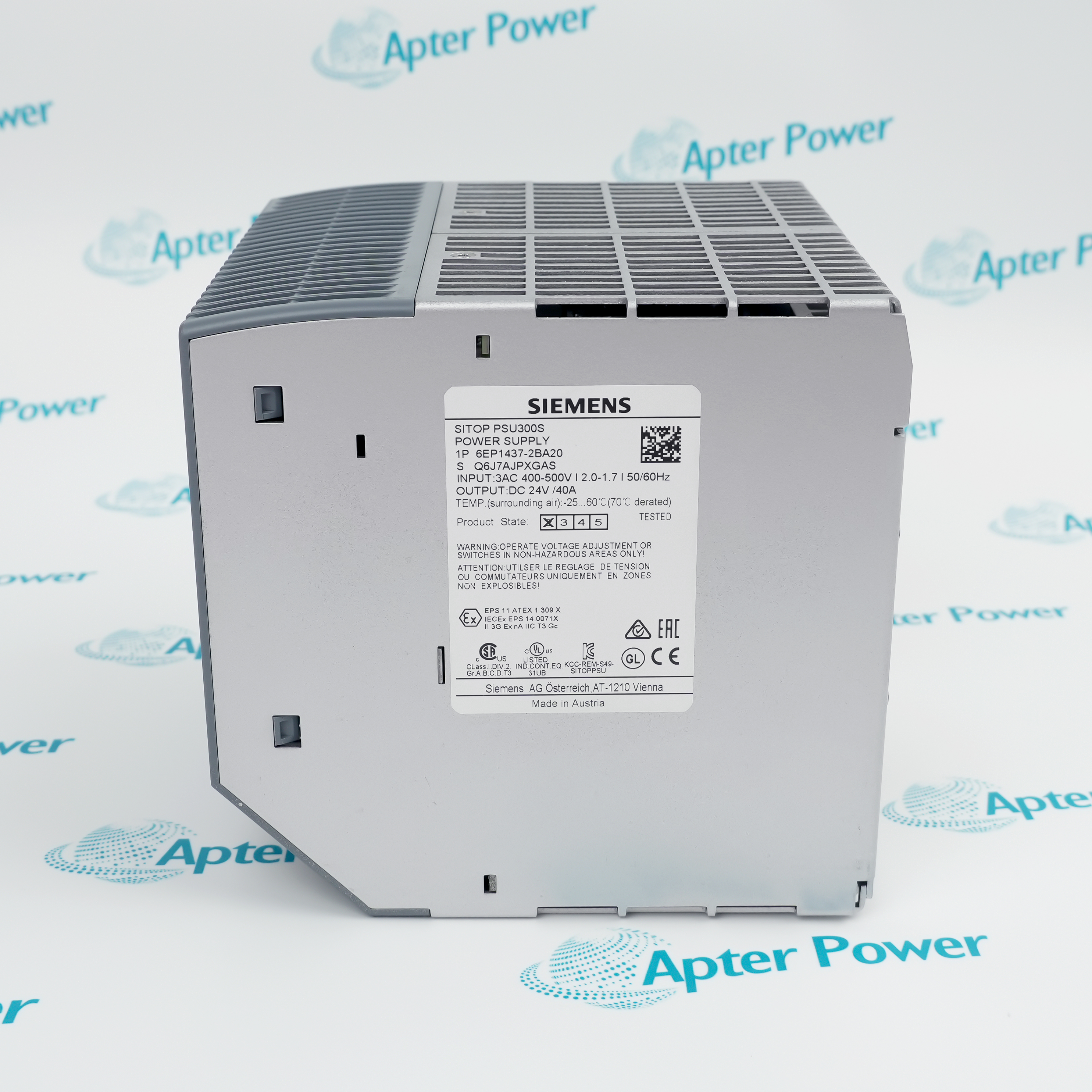
Match the complete marking
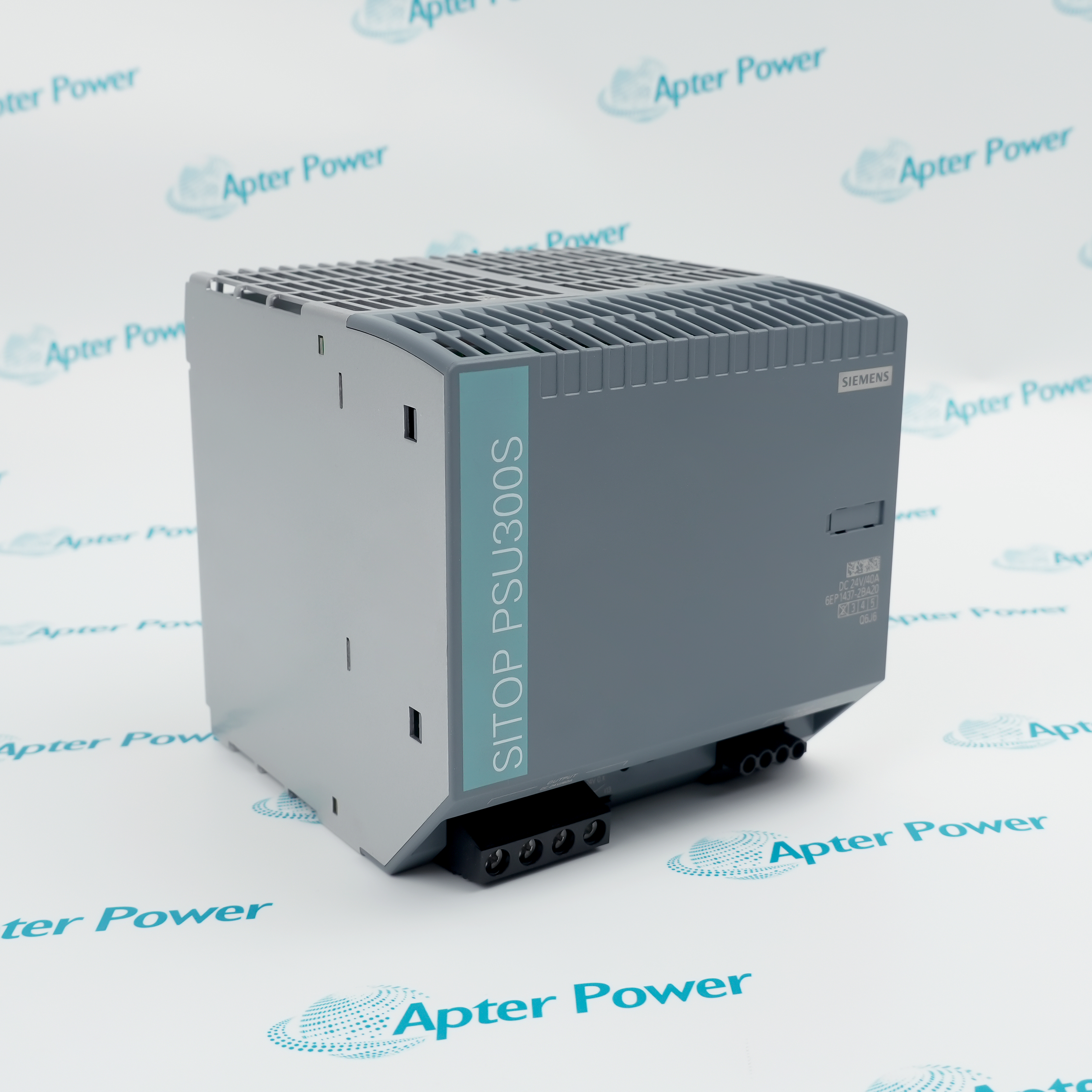
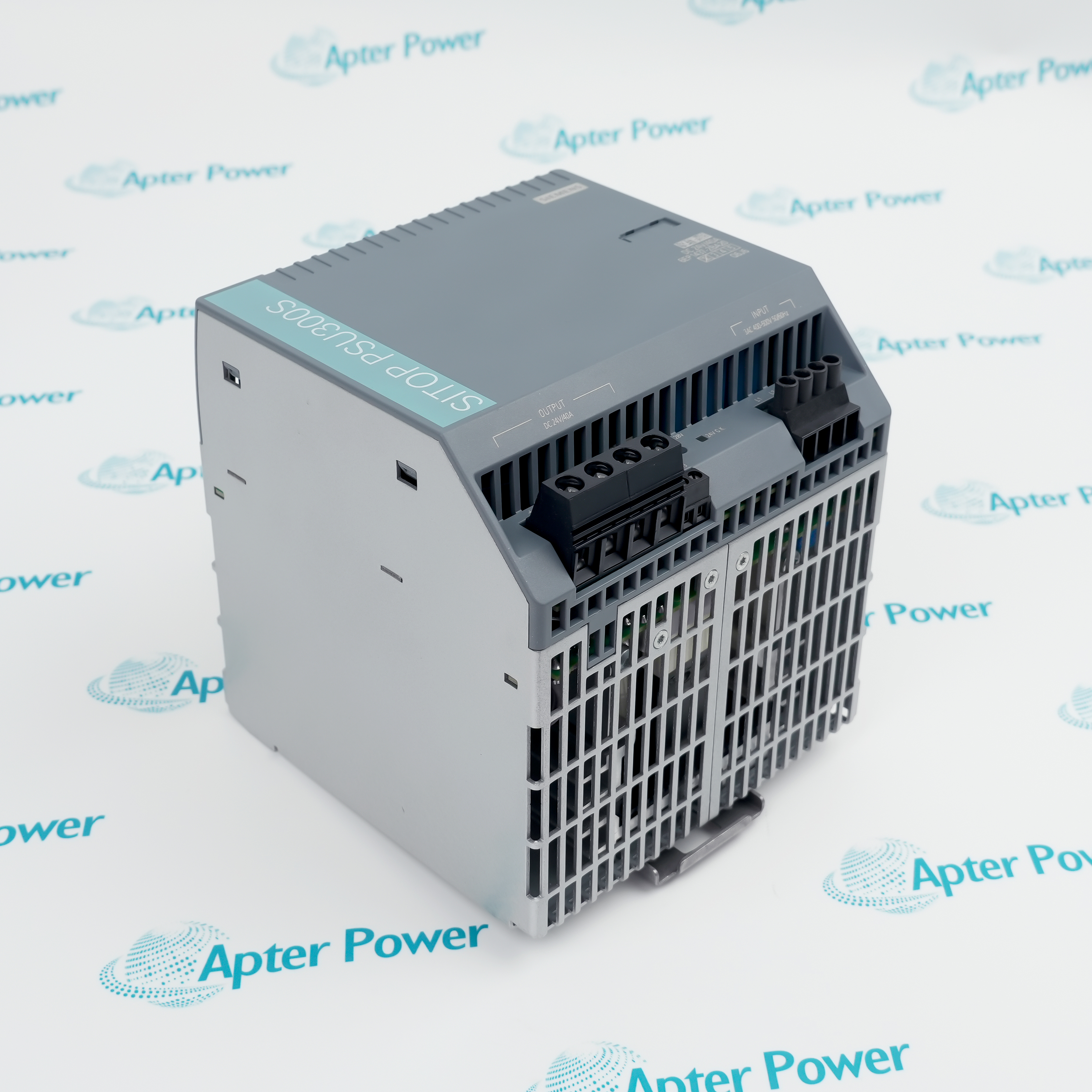
Include the complete 6EP1437-2BA20 marking, hardware state and required input/output arrangement.
-
Check the offered item before ordering
Request nameplate and terminal photographs. Have your maintenance team compare the offered 6EP1437-2BA20 with the installed supply and applicable Siemens SITOP instructions.
Technical specifications for 6EP1437-2BA20
-
Manufacturer:Siemens
-
Product Category:General Automation
-
Spare Part Number:6EP1437-2BA20
-
Weight:6.834 lbs (3.1 kg)
-
Tariff Code:8537101101
-
Input network:Three-phase AC
-
Rated input:400–500 V AC
-
Input voltage range:340–550 V AC
-
Line frequency:47–63 Hz
-
Input current:2 A at 400 V; 1.7 A at 500 V
-
Inrush current limit:60 A maximum at 25 °C
-
Input I²t:3.4 A²s maximum
-
Integrated input fuse:None; external protection required
-
Rated output:24 V DC / 40 A
-
Output adjustment:24–28 V; observe 960 W limit
-
Static voltage tolerance:±3%
-
Static line/load regulation:Approximately 1% / 2%
-
Residual ripple:150 mV peak-to-peak maximum
-
Voltage spikes:240 mV peak-to-peak maximum, 20 MHz bandwidth
-
Starting delay:1.5 s maximum
-
Voltage rise:15 ms typical; 500 ms maximum
-
Extra Power:60 A for 5 s per minute
-
Short-circuit pulse:65 A typical for 100 ms; every 2.5 s during operation
-
Current limitation:50 A typical
-
Short-circuit RMS current:14 A maximum
-
Mains buffering:6 ms minimum at 400 V and rated load
-
Output-ready threshold:Above 20 V ±0.5 V
-
Output-ready contact:Normally open; 30 V AC/0.5 A, 60 V DC/0.3 A or 30 V DC/1 A
-
Operating ambient:−25 to +70 °C; EZ 1: −10 to +70 °C; derating applies
-
Temperature derating:3% of rated current/K from +60 to +70 °C
-
Humidity:5–95%, non-condensing
-
Parallel power increase:2 units; matched settings and wiring
Information
- Siemens 6EP1437-2BA20 separates the three-phase input from the low-voltage control distribution. Its load-recovery behavior and output-state contact help the control system distinguish an adequate DC supply from a sustained overload.
Automatic overload recovery: A sufficiently depressed output triggers repeated restart attempts while the fault remains.
Independent state contact: A normally open relay reports the output-ready condition to an external monitoring circuit.
The output maintains regulation until current limitation is reached. Under overload, voltage and current fall; below approximately 10 V the supply switches off and attempts to restart. This can produce cyclic recovery at a faulted distribution network, so the waveform and branch states are more informative than a single handheld voltage reading.
The output-ready relay and green LED indicate the local supply state. They do not prove voltage at a remote load or selective operation of downstream protection. Mounting orientation, ventilation and hardware state affect environmental capability; EZ 1 units have a different lower operating-temperature limit from later hardware.
6EP1437-2BA20 Official Power Supply Manual Excerpt
Original English Siemens electrical ratings, operating modes and installation conditions for this exact article number. PDF · 10 pages.6EP1437-2BA20 Installation & Verification Guide
Apter Power commissioning workbook covering supply selection, DC distribution, operating-state checks and load acceptance. PDF · 5 pages.
Application scope: Select the unit against continuous load, transient demand and recovery requirements. In parallel systems, voltage alignment and equal path impedance support sharing, while a redundant system also needs decoupling and sufficient surviving capacity.
Three-phase control power
Supply a DC distribution network where the protected feeder lies within the specified three-phase range.Defined short-duration demand
Accommodate permitted transient peaks while keeping continuous and time-limited load budgets separate.Output-state monitoring
Connect the isolated output-ready contact to a correctly rated monitoring input for supply-state supervision.Coordinated supply resilience
Combine suitable decoupling or buffering equipment with the supply when the process requires fault tolerance or longer ride-through.
Verify coordinated three-pole feeder protection; the unit has no integrated input fuse.
Mount vertically with terminals below and at least 40 mm clear above and below.
Set output voltage safely and check the permissible voltage of every connected load.
Check branch protection against pulsed short-circuit behavior and the actual cable impedance.
Do not budget simultaneous Extra Power from multiple supplies as guaranteed system capacity.
Apply the actual EZ-dependent low-temperature limit and installation conditions.
Alternative Names
Technical notes
Cyclic fault response: A repeating output collapse and recovery can be the intended restart behavior under a persistent overload. Check faulted branches before replacing the supply.
Remote voltage budget: The output-ready threshold is a local status threshold. Cable drop and protection-device losses still determine voltage at the consuming device.
Redundant capacity: Parallel power increase and redundancy are different designs. Decoupling and adequate remaining capacity are necessary when one supply is lost.

FAQ View All FAQ
-
Why can 6EP1437-2BA20 produce repeated voltage pulses into a faulted DC bus?When overload depresses the output below approximately 10 V, the supply switches off and restarts automatically. Inspect branch currents and fault paths during the cycle rather than treating a low average voltage as proof of a failed converter.
-
Can two units of 6EP1437-2BA20 be sized by adding both Extra Power ratings?No. The simultaneous short-term overload capability of parallel supplies must not be counted when configuring the system. Size the continuous load and verify the actual transient profile with the coordinated arrangement.
-
How much continuous current remains at a 28 V setting on 6EP1437-2BA20?The 960 W output boundary gives about 34.3 A from 960/28 before other temperature, mounting or system limits. Raising voltage does not preserve an unrestricted 40 A output across the adjustment range.
-
Would the output-ready contact of 6EP1437-2BA20 safely switch any PLC or relay circuit?Only a circuit within the contact’s AC or DC rating is suitable. Check voltage, load current and switching characteristics; the allowable current changes with the circuit voltage and must not be taken from a different rating line.
-
How should branch-fuse selection account for the restart behavior of 6EP1437-2BA20?Compare the available pulse current and duration with the protection device’s clearing behavior and cable impedance. A current-limited supply may fail to clear an ordinary branch fuse promptly, so evaluate selective protection under the actual fault conditions.
-
Does a redundant pair of 6EP1437-2BA20 remain redundant if both units are already fully loaded?No. The surviving supply path must support the required load after a failure. Include correctly rated decoupling and verify the remaining capacity; a power-increase parallel connection is not automatically an N+1 arrangement.
-
What needs checking before using an EZ 1 version of 6EP1437-2BA20 in a cold cabinet?Its lower operating limit is −10 °C rather than the −25 °C limit given for later hardware. Confirm the actual product state and worst cabinet temperature; storage limits do not authorize operation below the applicable boundary.
-
Can the six-millisecond mains buffer of 6EP1437-2BA20 replace a DC UPS?No. That minimum applies at 400 V input and rated load and only addresses a brief interruption. Compare the process ride-through requirement with the actual load and add suitable buffering or UPS equipment where needed.
Supporting new and legacy automation
-
Please try to be as accurate as possible with your search.
-
We can quote you on 1000s of specialist parts, even if they are not listed on our website.
-
We can't find any results for “”.
Related cases and sourcing guidance
View all case studiesYou May Also Like
Product Browsing History
-
Whatsapp: +86 18030235313
Send us a message. -
sales13@apterpower.com
Complete our online form. -
+86 18030235313
Speak to our team in your native language.