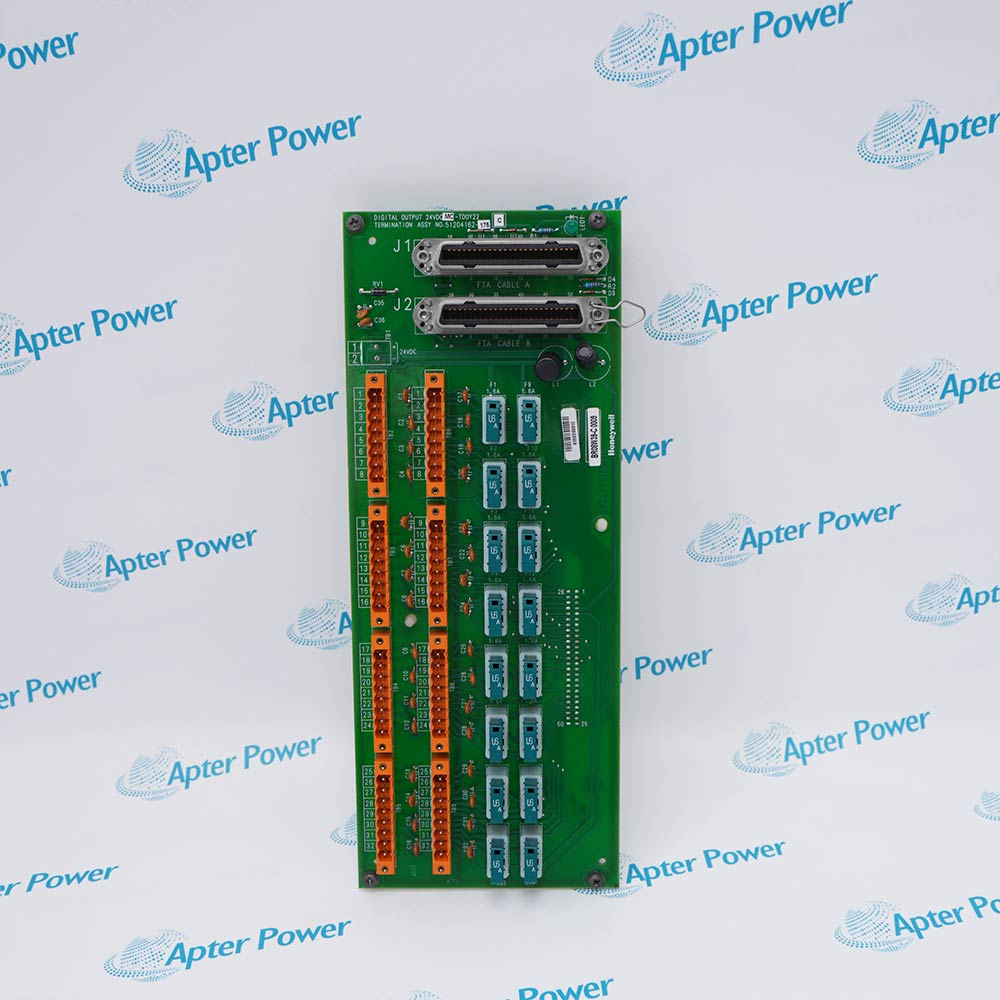
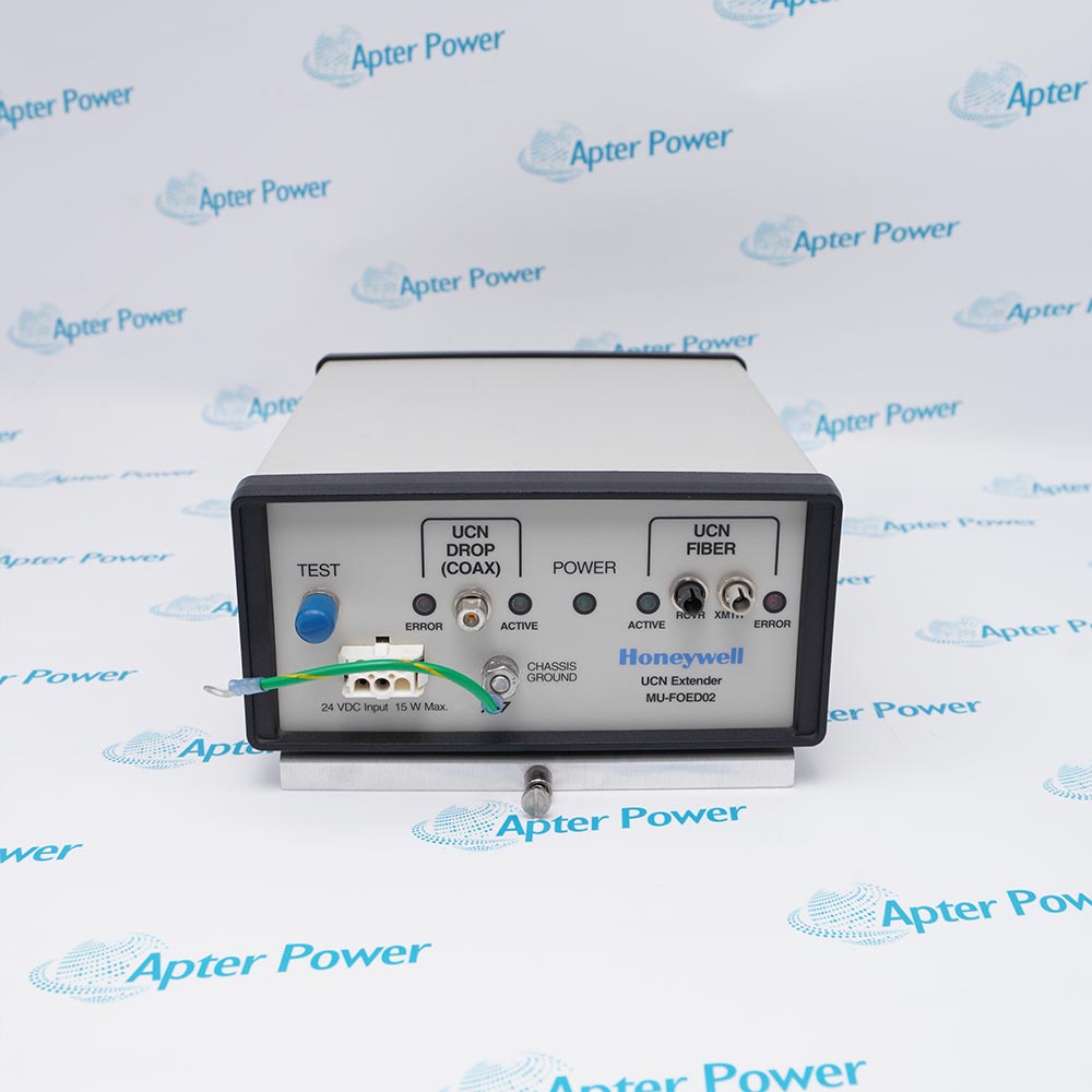
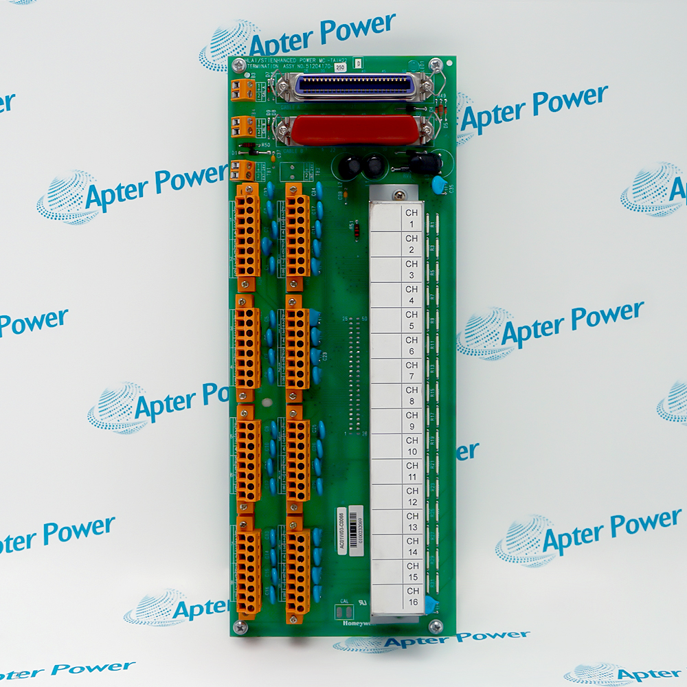
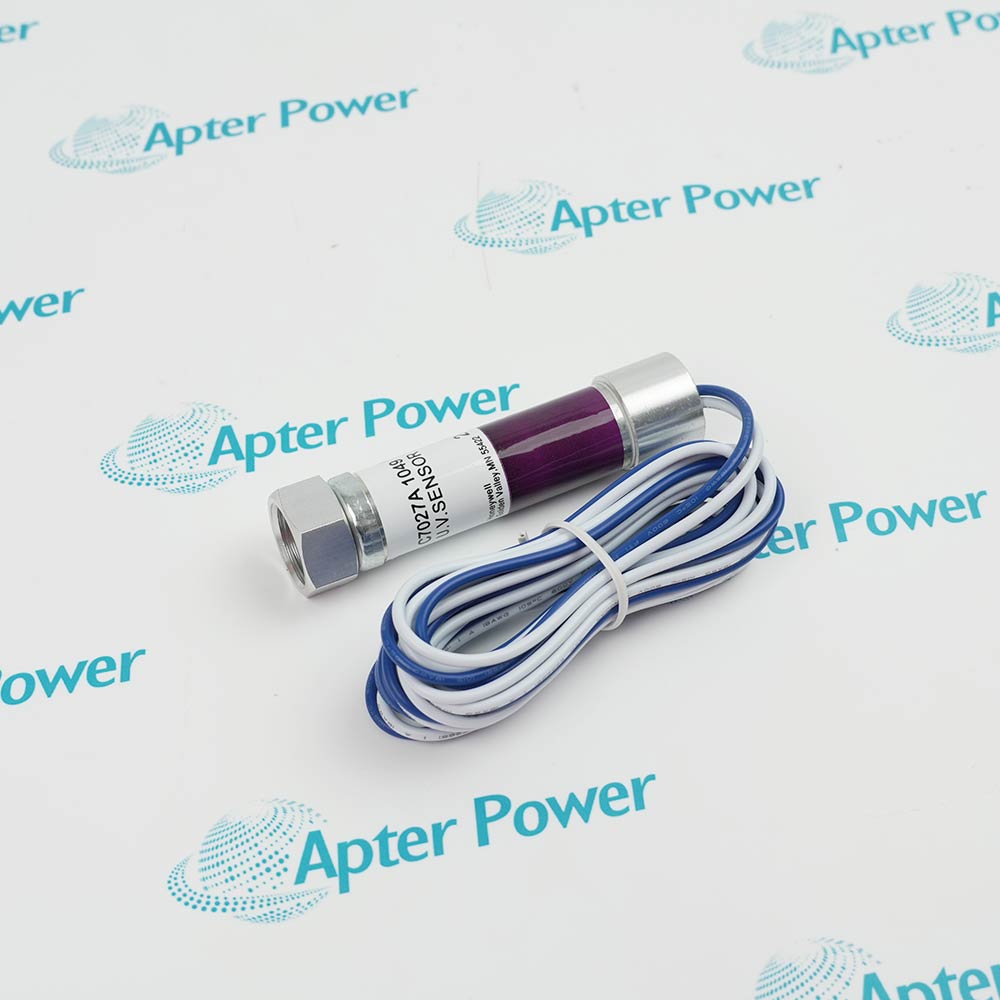
Honeywell 10001/R/1 is an FSC vertical bus driver used between the Central Part and the I/O level.
- System: Honeywell Fail Safe Controller
- Function: Vertical bus driver
- Configuration: Relay-equipped VBD for documented FSC arrangements
- Lifecycle: Phased Out support from December 31, 2025
Use 10001/R/1 only with the exact host, rack or chassis, terminal hardware, cable and project configuration specified for the installed system. Before replacement, match the complete physical label, revision, connectors, field wiring and approved engineering documents. Isolate energy, back up the configuration where applicable, and complete documented post-installation functional checks before return to service.
Confirm the complete physical label, host system, terminal hardware, cable and project documentation before installation or replacement.
Apter Power 10001/R/1 Manuals and Guides
Important Notice: The first link is the model-specific product-parameters PDF prepared from the directly relevant product evidence; the second link is the Apter Power product information manual. Confirm the physical nameplate, current Honeywell documents, and host-system requirements before installation or replacement.
Installed-base maintenanceSupports identification and maintenance planning for Honeywell 10001/R/1.
Compatibility reviewCompares the exact hardware, host, rack or chassis, terminal assembly, cable and revision before replacement.
Installation planningDefines the isolation, mounting, wiring and configuration checks required before field work.
Commissioning and troubleshootingSupports controlled power, communication, channel, diagnostic and alarm checks after work.
Read the exact product and installed-system instructions before work. Verify the complete physical label and configuration.
1Verify the complete Honeywell 10001/R/1 physical label before use.
2Use 10001/R/1 only with the exact host, rack or chassis, terminal hardware, cable and project configuration specified for the installed system.
3Confirm the exact rack or chassis position, terminal assembly, cable, connector, power and project revision.
4De-energize the equipment unless the exact hardware manual and site procedure explicitly permit energized service.
5Back up controller, communication and I/O configuration before replacement or migration work.
6Do not transfer electrical, communication or mechanical values from a related model or different suffix.
7Follow ESD controls and protect connectors, terminals and field wiring during handling.
8Perform documented visual, wiring, power, communication, channel, diagnostic and fail-state checks after installation.


 Videos
 News
News Applications