-
Match the complete marking
Include PR9350/02 and any revision or assembly number visible on the item. Keep the exact reference on your enquiry and quotation.
-
Check the offered item before ordering
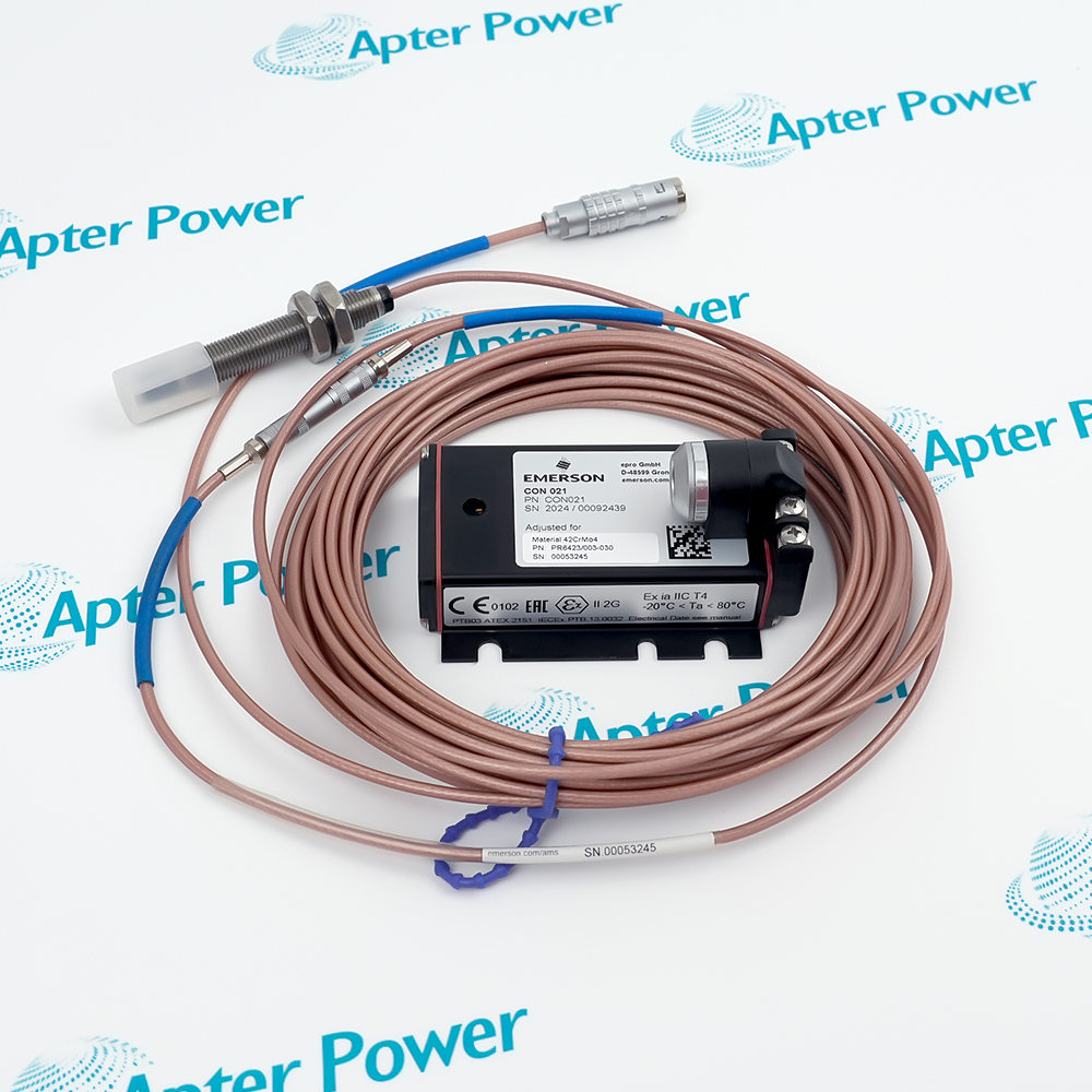
Request current label, body and cable-connector photos. Have your maintenance team compare the offered PR9350/02 with the installed equipment and applicable Emerson documentation.
Technical specifications for PR9350/02
-
Manufacturer:Epro
-
Product Category:Machinery Monitoring Systems
-
Spare Part Number:PR9350/02
-
Weight:1.66 kg
-
Tariff Code:8537101190
-
Transducer family:PR9350 inductive displacement
-
Nominal measuring range:−25 to +25 mm
-
Sensitivity:270 mV/V
-
Excitation:5 V rms
-
Supply current:27–50 mA
-
Carrier frequency:3–5 kHz
-
Connection:Three-pole sensor connector
-
Mounting:Internal M4 fixing holes; M3 tracing-pin end
-
Dynamic measurement limit:Up to 1250 Hz
-
Preferred converter:A6500-LC LVDT Converter
-
Preferred measurement card:A6500-UM Universal Measurement Card
-
Sensor housing:Hermetically encapsulated
Information
- The PR9350/02 transducer converts controlled linear travel into an inductive measurement for a suitable excitation and amplifier channel.
System dependency: Carrier excitation and amplifier
Commissioning check: Verify mechanical zero and end travel
The housing mounts through internal M4 fixing holes and the tracing-pin end uses an M3 mechanical connection to the moving target. The installed linkage, stroke and zero point must be engineered so that the sensor remains inside its operating range throughout the machine cycle.
Before replacement, identify the existing connector and amplifier, record the calibrated zero and mechanical travel, and inspect the moving contact for binding. After installation, check both travel directions and the amplifier reading against a known reference position.
-
Epro PR9350/02 technical reference
Apter Power technical reference - PDF, 2 pages. Product identity, verified interface data and applicability conditions. -
Epro PR9350/02 installation guide
Prepared by Apter Power - PDF, 1 page. Configuration review, safe installation and functional acceptance.
Compatibility scope: Pair the ±25 mm /02 execution with suitable excitation and input electronics; verify stroke, fixing points and connector orientation.
Turbine expansion
Follow controlled casing or shaft expansion with a suitable mechanical linkage and inductive monitor input.Differential expansion
Measure relative movement between machine structures when the mounting geometry and reference point are defined.Valve or actuator travel
Track bidirectional movement within the approved stroke and mechanical contact arrangement.MMS6410 input
Provide an inductive displacement signal to a configured MMS6410 measuring channel where the sensor/excitation match is verified.
Ensure the full mechanical motion remains within the transducer range and does not overdrive the tracing pin.
Use the designed fixing points and prevent body movement relative to the reference structure.
Match the amplifier carrier and connection to the sensor’s required supply.
Confirm the three-pole pin assignment and cable condition.
Establish the approved center position without loading the tracing pin sideways.
Apply known positive and negative displacements and compare the indicated values.
Alternative Names
Technical notes
Technical basis: Emerson PR9350 / K20-315 Linear Displacement Transducer Installation Guide, MHM-97864 Rev 1.6, March 2026.
Applicability: The stated ratings apply to PR9350/02 in the Emerson PR9350/K20-315 guide. Confirm the supplied connector, fitted execution and mounting arrangement.
Mechanical relationship: The M4 body fixation and M3 tracing-pin connection establish the reference and moving points. The linkage must allow the full intended travel without side loading or overdriving the pin.

FAQ View All FAQ
-
How is the center position established for PR9350/02?Set the machine linkage at the approved mechanical reference, then align the transducer and amplifier zero without side loading.
-
What can cause nonlinear travel readings from PR9350/02?Overtravel, binding, an incorrect carrier, wiring faults or misaligned linkage can distort the response; test both directions.
-
Can PR9350/02 be connected to a DC input directly?It is an inductive transducer requiring suitable carrier excitation and demodulation; use an approved compatible amplifier.
-
How is a reversed signal from PR9350/02 investigated?Check connector polarity, linkage motion direction and amplifier channel configuration against the original installation.
-
What mechanical check protects PR9350/02 during service?Verify end-to-end travel and stop positions so the tracing pin is not forced beyond its permitted stroke.
-
How is PR9350/02 tested after mounting?Move through known reference positions in both directions and compare the amplifier indication with actual displacement.
-
Which companion module can read PR9350/02?MMS6410 is a documented inductive displacement measuring amplifier; verify the installed revision and sensor setup.
-
What records should be retained for PR9350/02?Keep mounting geometry, linkage details, zero position, amplifier settings and the measured travel baseline.
Supporting new and legacy automation
-
Please try to be as accurate as possible with your search.
-
We can quote you on 1000s of specialist parts, even if they are not listed on our website.
-
We can't find any results for “”.
Related cases and sourcing guidance
View all case studiesYou May Also Like
Product Browsing History
-
Whatsapp: +86 18030235313
Send us a message. -
sales13@apterpower.com
Complete our online form. -
+86 18030235313
Speak to our team in your native language.