-
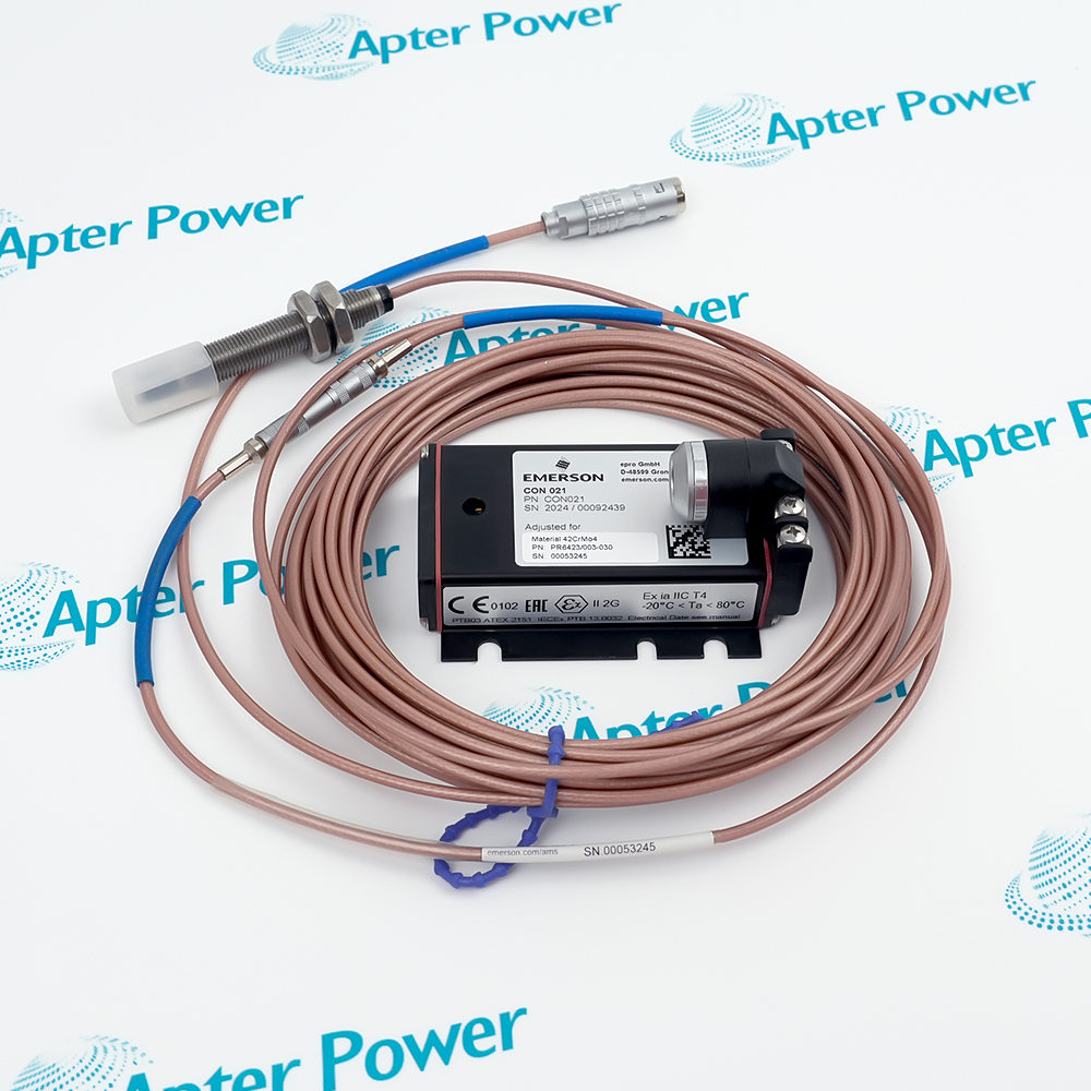
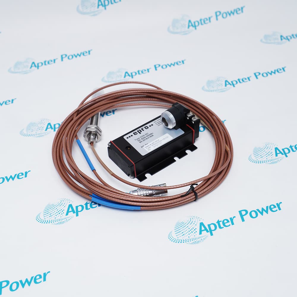
Match the complete marking
Match A6500-UM, revision and visible labels.
-
Check the offered item before ordering
Confirm AMS 6500 machinery protection system, companion hardware and wiring.
Technical specifications for A6500-UM
-
Manufacturer:Epro
-
Product Category:Machinery Monitoring Systems
-
Spare Part Number:A6500-UM
-
Weight:0.2 kg
-
Tariff Code:8537101190
-
Measurement channels:2
-
Board format:100 mm x 160 mm
-
Rack width:6 HP
-
Rack height:3 RU
-
Power consumption:6 W maximum
-
Protection degree:IP20
-
Operating temperature:-20 to +70 deg C
-
Storage temperature:-40 to +85 deg C
-
Relative humidity:5 to 95%, non-condensing
-
Vibration resistance:1 mm peak-to-peak at 2 to 13.2 Hz; 0.7 g at 13.2 to 150 Hz
-
Shock resistance:15 g, 11 ms
Information
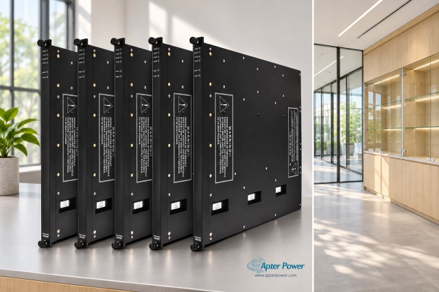
- A6500-UM conditions two configured machinery signals and applies channel-specific measurement, alarm and voting logic within the AMS 6500 protection rack.
On-card protection logic: Alert, danger, channel-OK and voting behavior are evaluated within the protection system.
Live diagnostic access: Buffered signals and status support commissioning and fault isolation without changing the machine channel.
The card processes dynamic or position signals and exposes measurement, status and buffered outputs to the protection architecture. A replacement must receive the verified parameter set rather than a default channel template.
Before exchange, export the rack configuration and collect gap, baseline and alarm-state evidence. After fitting, verify card recognition, sensor supply, channel OK, static values, dynamic response and configured relay logic.
A6500-UM Technical Data Reference
Emerson A6500-UM Universal Measurement Card operating manual MHM-97873; selected exact-model and documented family data for A6500-UM.A6500-UM Installation & Verification Guide
Model-specific installation, wiring, inspection and commissioning checks for A6500-UM.
Application scope: Configuration boundary: Channel setup, rack slot, relay voting and the matched transducer chain must correspond to the protected machine point.
Relative shaft vibration
Process compatible eddy-current transducer signals for machinery protection.Axial or radial position
Track static displacement within the approved sensor and scale relationship.Bearing vibration
Condition compatible seismic-sensor signals under the selected measurement mode.Rack modernization and service
Restore two configured channels with their alarm and voting relationships.
Retain transducer, range, filters, alarms and voting.
Capture slot, neighboring cards and relay logic.
Measure supply, gap and baseline before removal.
Protect the board and backplane contacts.
Do not copy a neighboring channel template.
Verify OK, alert, danger and configured voting.
Alternative Names
Technical notes
Channel-definition archive: Export transducer type, scale, filter, thresholds, delays, latching and voting separately for both channels.
Live-signal comparison: Compare sensor supply, bias or gap and buffered waveform with the accepted machine baseline.
Protection-chain release: Prove channel OK, alert, danger and configured relay action before restoring automatic operation.

FAQ View All FAQ
-
Which configuration items make the two channels of A6500-UM different?Transducer type, sensitivity, range, filter, alarm thresholds, delays, latching and voting can all differ by channel.
-
How should the pre-removal baseline for A6500-UM be recorded?Capture sensor supply, static gap or bias, dynamic amplitude, phase where used, channel OK and active alarm states.
-
Why is a default configuration unsafe for A6500-UM?The card is universal; a default may apply the wrong transducer scale, measurement mode or protection thresholds.
-
What does a channel-not-OK state on A6500-UM require?Check sensor supply, wiring, transducer gap, configured limits and the card input before changing alarm settings.
-
How should buffered outputs from A6500-UM be used during commissioning?Compare the live waveform with the machine baseline and rack measurement without disturbing the protection path.
-
What rack evidence should accompany A6500-UM?Retain slot number, firmware or revision, rack configuration version, companion relay logic and approved machinery channel list.
-
How are alert and danger functions of A6500-UM proven?Inject or simulate only approved signal levels and confirm threshold, delay, latch, reset and relay-voting response.
-
Which protection-channel results are required before releasing A6500-UM?Require stable channel OK, correct static and dynamic readings, verified alert and danger action, relay-voting response and an archived final configuration.
Supporting new and legacy automation
-
Please try to be as accurate as possible with your search.
-
We can quote you on 1000s of specialist parts, even if they are not listed on our website.
-
We can't find any results for “”.
Related cases and sourcing guidance
View all case studiesYou May Also Like
Product Browsing History
-
Whatsapp: +86 18030235313
Send us a message. -
sales13@apterpower.com
Complete our online form. -
+86 18030235313
Speak to our team in your native language.