Blog
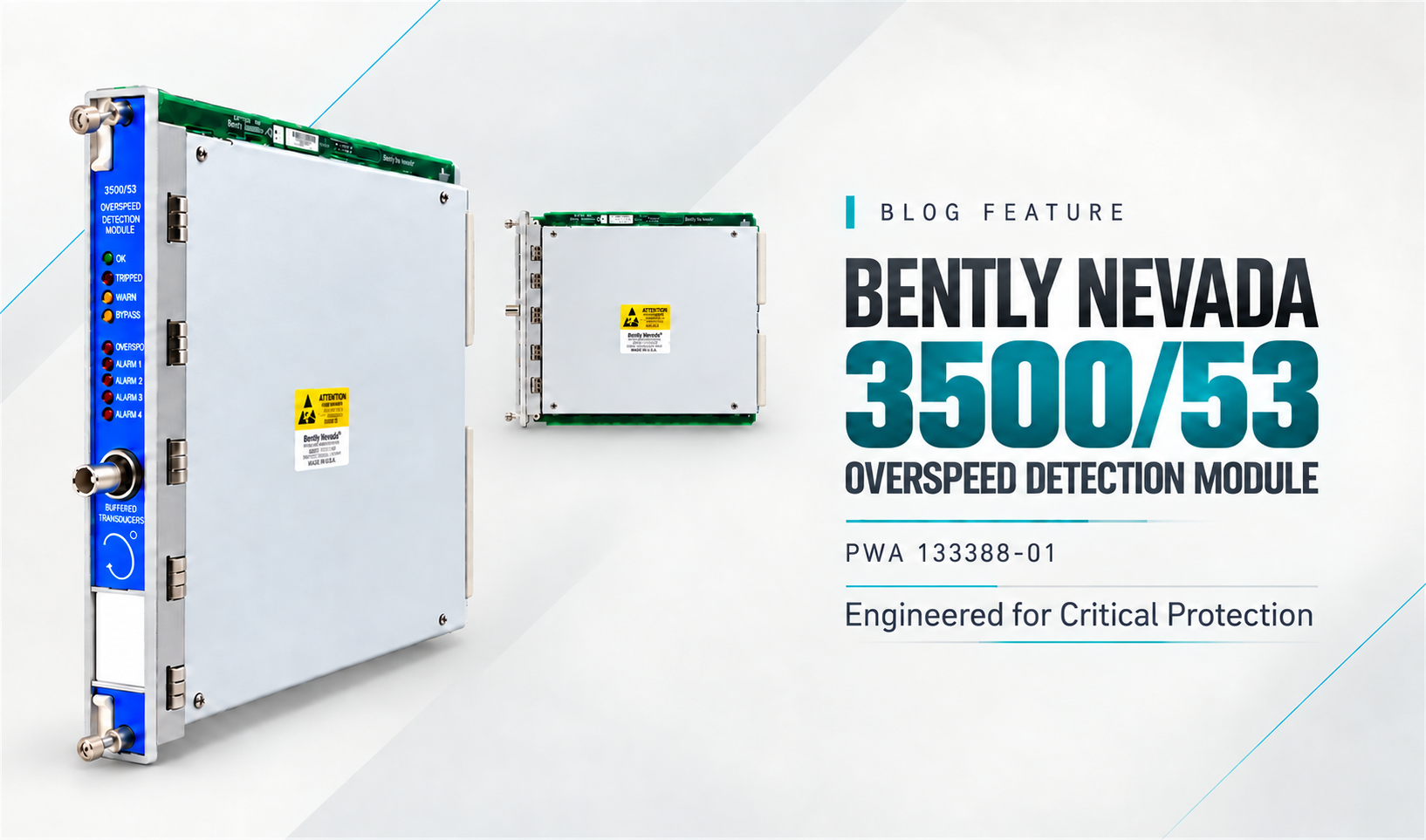
Bently Nevada 3500/53 133388-01: Overspeed Module Replacement and Proof-Test Planning
Replacing a Bently Nevada 3500/53 133388-01 requires more than fitting a spare that powers up.
Before return to service, the asset owner needs documented evidence that the correct front module and associated I/O are installed, the approved configuration is restored, voting and bypass states match the controlled design, and the required trip path passes the site's proof test. Turbine protection engineers, outage planners, and MRO buyers should define those records before requesting a quote. We can document the offered hardware and supplier-side checks, while installation and safety-function approval remain with the authorized site team.
Where Does the 3500/53 Fit in an Overspeed Protection System?
The 3500/53 is not a general-purpose speed display. Baker Hughes describes it as a fast-response, redundant tachometer system intended specifically for use in overspeed protection. Modules can be combined in two-out-of-two or two-out-of-three voting arrangements; the OEM application guide recommends two-out-of-three for the application it describes and states that the system requires a 3500 rack with redundant power supplies. It also distinguishes the overspeed detector as protection for the driver rather than the driven machine. See the OEM centrifugal compressor application guide .
That context changes the replacement question. A matching front-module number is only one part of the protection chain:
Speed sensors and their field wiring provide the input signals.
The installed 3500/53 channels process those signals against the approved configuration.
The site's voting arrangement determines how channel states contribute to a trip demand.
Relay, shutdown, or emergency-shutdown interfaces pass the demand onward.
Final elements act according to the plant's approved protection design.
A spare can be genuine, functional on a bench, and still be unsuitable for a specific installation if its identity, revision, associated I/O, configuration basis, or approval requirements do not match the controlled design record.
There is also an important lifecycle boundary. Baker Hughes states that the 3500/53 is included in its application guidance to support the existing installed base and is no longer available for new installations; it directs future Bently Nevada overspeed and emergency-shutdown applications toward the 3701/55 ADAPT ESD. The scope here is maintenance of an installed 3500/53 system, not specification of 133388-01 for a new protection architecture.
What Must Be Captured Before Removing 133388-01?
Build an as-found record before any component is disturbed. The record should let a second qualified engineer reconstruct what was installed, how it was configured, which protective paths were available or bypassed, and what evidence was used to approve the work.
At minimum, capture the following:
Evidence to capture
What to record
Why it matters
Front module identity
Full faceplate and side-label photos, part number, assembly/revision information, serial number, slot
Connects the installed unit to the work order and replacement decision
Associated I/O
Full rear I/O label, termination style, connector positions, wiring identifiers
Prevents a front-card-only comparison from hiding an I/O or termination mismatch
Rack baseline
Rack type, power-supply arrangement, relevant interface modules, adjacent protection modules
Establishes the actual system environment rather than an assumed catalog configuration
Configuration record
Controlled backup/export, channel settings, alarm/trip setpoints, configuration checksum or revision record where available
Provides the approved reference for restoration and comparison
Protection state
Voting arrangement, active bypasses, inhibits, channel defeat states, maintenance overrides
Shows what protection remains available during the work
External interfaces
Relay or shutdown path references, ESD/DCS interface drawings, annunciation points
Defines the downstream functions that the post-installation test must address
Operating evidence
Relevant alarms, system events, fault codes, and time-stamped as-found observations
Helps distinguish a failed module from a sensor, wiring, configuration, or system-level problem
Governance
Approved work order, risk assessment, management-of-change record, responsible approvers
Makes the change traceable and establishes stop-work authority
The current 3500 System Datasheet explains that 3500 modules use associated I/O modules, store configuration in non-volatile memory, and record configuration changes in the system event list. Those capabilities are useful evidence sources, but they do not replace the site's controlled backup, drawings, or approval record.
Document Voting, Bypass, and Trip Interfaces
Do not reduce the as-found state to “two-of-three” or “two-of-two.” Record how the installed channels, bypasses, and outputs actually interact in the approved site design.
The pre-removal package should answer these questions:
Which modules and sensor channels participate in the overspeed vote?
Is any channel already bypassed, inhibited, faulted, or under maintenance?
What protection remains while one module is removed?
Which contacts or downstream interfaces carry the trip demand?
Which alarms indicate a channel fault, bypass, or loss of protection?
Who has authority to apply and remove each bypass?
What independent safeguards or operating restrictions are required during the impairment?
What constitutes a failed restoration, and who can stop return to service?
These are documentation and approval questions, not instructions to change the voting logic. If the current state does not agree with the approved cause-and-effect, logic narrative, or trip drawing, stop and resolve that discrepancy before using the maintenance window to introduce another change.
Confirm the Module, I/O, and Firmware Revision
Treat “3500/53 133388-01” as the beginning of identification, not the entire identity. The current Baker Hughes 3500 manuals index identifies document 134939 for the 3500/53 Overspeed Detection System. Use the revision of that manual applicable to the installed system, together with the site's approved records, to verify the required front module, associated I/O, firmware, software tools, approvals, and rack prerequisites.
Use a two-sided comparison before releasing the spare:
Installed side
Proposed spare side
Full part and assembly identifiers
Full part and assembly identifiers
Hardware revision
Hardware revision
Firmware version or controlled firmware requirement
Installed firmware and evidence of version
Rear I/O part number and termination arrangement
Required I/O pairing and compatibility basis
Agency or hazardous-area requirements
Markings and documentation supplied for the quoted unit
Approved configuration baseline
Method and authority for loading or verifying that baseline
Do not infer compatibility from a reseller title, a similar faceplate, or a shortened “3500/53 module” description. Preserve suffixes and revision details in the RFQ and purchase order. Where the OEM record and the physical labels do not agree, keep the item on engineering hold .
Which Safety Reviews Are Required Before Replacement?
A controlled replacement should pass four reviews before field work begins. The names of the reviews may differ by site, but the decisions should be explicit.
Review gate
Minimum decision
Typical owner
Release evidence
Protection impairment review
The plant can manage the period in which the channel or vote is unavailable
Operations and turbine protection
Approved impairment plan, bypass register, operating restrictions
Change-control review
The spare and planned configuration are within the approved design basis, or the change has been formally assessed
Functional-safety or controls authority
MOC/work-order approval and design references
Work execution review
Isolation, electrostatic-discharge controls, access, tools, and responsibilities are defined
Maintenance supervisor
Permit, job plan, toolbox review
Restoration review
Test scope, acceptance criteria, witnesses, records, and rollback action are agreed before installation
Asset owner/authorized engineer
Approved proof-test package and sign-off sheet
The review must distinguish a like-for-like maintenance action from a design change. A new revision, different I/O arrangement, altered firmware, changed trip setpoint, or revised voting philosophy may trigger additional engineering and functional-safety review even if the front panel fits the same rack slot.
Do not use a general certification claim as a shortcut. Baker Hughes' published TÜV notice says certification applies to specific 3500/53 configurations and that SIL determination depends on assessment of the system and application. It does not make every loose 133388-01 module, every rack configuration, or every field replacement automatically “SIL 3.” Review the Bently Nevada functional-safety notice and the safety documentation applicable to the installed configuration.
How Should the Spare Be Bench-Checked?
The bench check should answer a limited question: is the received unit correctly identified, physically acceptable, and capable of completing the supplier's or site's defined pre-installation checks? It cannot validate the complete field protection function.
Use a serial-number-linked incoming inspection record:
Compare the delivered label, assembly number, revision, and serial number with the purchase order and approved compatibility record.
Photograph the actual unit from enough angles to show labels, connectors, card edges, extraction hardware, and visible condition.
Inspect for contamination, corrosion, impact damage, bent or damaged connectors, broken fasteners, unauthorized markings, or evidence of poor handling.
Verify the declared condition, such as new, surplus, or repaired, and record any packaging, preservation, or repair documentation supplied.
Review the test report for the exact checks performed, equipment or fixture identification where provided, test date, result, and the serial number of the unit tested.
If site-approved facilities and procedures allow a power-up or self-test, record the setup and observed status without extending the result beyond that test's scope.
Quarantine the unit if the labels, physical condition, documentation, or test identity do not agree.
The wording of the acceptance record matters. “Powered on” means only that the unit powered in the stated setup. “Self-test passed” means only that the documented self-test completed. Neither statement proves correct sensor response, approved trip setpoints, voting behavior, downstream relay operation, final-element action, or suitability for the installed safety function.
This evidence boundary should also appear in the supplier's quotation. A vague “fully tested” claim is less useful than a traceable report that states exactly what was and was not tested.
What Does a Valid Post-Installation Proof Test Include?
A valid proof test is based on the asset owner's approved procedure and the installed system's safety requirements. The test stimulus, numerical values, expected time response, voting sequence, final-element scope, and acceptance criteria cannot be set by a generic blog or a parts supplier.
For planning purposes, the proof-test package should show how each of the following layers will be verified:
Test layer
Question the approved procedure must answer
Evidence to retain
As-left hardware
Is the approved module in the correct slot with the correct associated I/O and secure connections?
Label photos, installation inspection, torque/connection records where required by site procedure
Configuration
Does the as-left configuration match the approved baseline, including channel parameters and setpoints?
Configuration comparison, revision/checksum record, authorized sign-off
Sensor input path
Does each required channel receive and interpret the approved test stimulus correctly?
Calibrated test-equipment record, channel results, observed values/status
Channel diagnostics
Are normal, fault, and applicable diagnostic states detected and annunciated as expected?
Alarm/status record and exception log
Voting and bypass behavior
Does each approved test case produce the expected vote while bypasses and inhibits behave as documented?
Step-by-step result sheet tied to the cause-and-effect or logic record
Trip output path
Do the designated relays or ESD interfaces change state as required?
Contact/interface observations and time-stamped event evidence
Final element, if in scope
Does the shutdown device perform the required action under the approved test arrangement?
Witnessed functional-test result or documented reason for a separately scheduled test
Restoration
Are all test forces, jumpers, bypasses, inhibits, and temporary wiring removed, with protection returned to its approved state?
Independent check, bypass-register closure, final alarm/event review
Plan the proof test before the outage, not after the replacement has been fitted. Predefine who applies the stimulus, who observes each interface, who can accept deviations, and what happens if one layer fails. A front-panel healthy indication should never be the sole return-to-service criterion.
The final record should make failures visible. Do not convert an open issue into a pass by writing “functionally equivalent,” “as expected,” or “tested OK” without the underlying observations. Record actual results, deviations, corrective actions, retests, witnesses, date/time, and the approved as-left state.
What Should Procurement Ask the Supplier to Prove?
Procurement can reduce both schedule risk and technical ambiguity by asking for evidence that a supplier can reasonably control. It should not ask the supplier to certify site-specific compatibility or the completed safety function.
Ask the supplier to document
Keep with the asset owner
Exact quoted part number and all visible suffixes
Approval of the installed configuration
Actual-unit label and condition photos
Correct trip setpoints and voting philosophy
Serial number and hardware/revision details available from the unit
Compatibility with the site's exact rack, I/O, firmware, and design basis
Declared condition and repair history if applicable
Management of change and protection-impairment controls
Test scope, result, date, and link between the report and serial number
Field proof test of sensors, module processing, outputs, and final elements
Included accessories or I/O, stated line by line
SIL claim for the complete installed safety function
Warranty and return terms in the quotation
Authorization to return the turbine or driver to service
Current availability, dispatch basis, shipping terms, and export documents
Site acceptance and final sign-off
For an efficient RFQ, send Apter Power:
“ 3500/53 133388-01 ” exactly as shown on the requirement, without dropping the suffix.
Clear photos of the installed front module, side label, and associated rear I/O label.
Hardware and firmware details available from the site's controlled records.
Rack and slot information, required approvals, quantity, preferred condition, destination country, and required-on-site date.
The evidence package you require before shipment, such as actual-unit photos or a serial-linked test record.
Apter Power can then prepare a documented quotation based on the identified requirement and current sourcing position. Availability, condition, lead time, warranty, and included documentation should be confirmed in that quotation rather than assumed from a catalog image or an undated web listing. Browse the Apter Power Bently Nevada catalog or send the complete requirement to our team .
Return-to-Service Decision for 133388-01
A controlled 3500/53 133388-01 replacement has three separate acceptance decisions:
Hardware acceptance : the received module, revision, associated I/O, condition, and documentation match the approved requirement.
Configuration acceptance : the installed module is verified against the site's controlled baseline, with voting, bypasses, and interfaces correctly restored.
Safety-function acceptance : the approved post-installation proof test demonstrates the required sensor-to-output behavior, or sensor-to-final-element behavior where specified, and leaves an auditable record.
None of these decisions can substitute for the others. Supplier evidence can establish the identity and stated condition of a spare. It cannot prove the performance of the installed overspeed protection function. Keep procurement evidence, engineering approval, change control, and site proof testing connected, but assign each decision to the party qualified to make it.


 Videos
 News
News Applications









Leave Your Comment