-
Match the complete marking
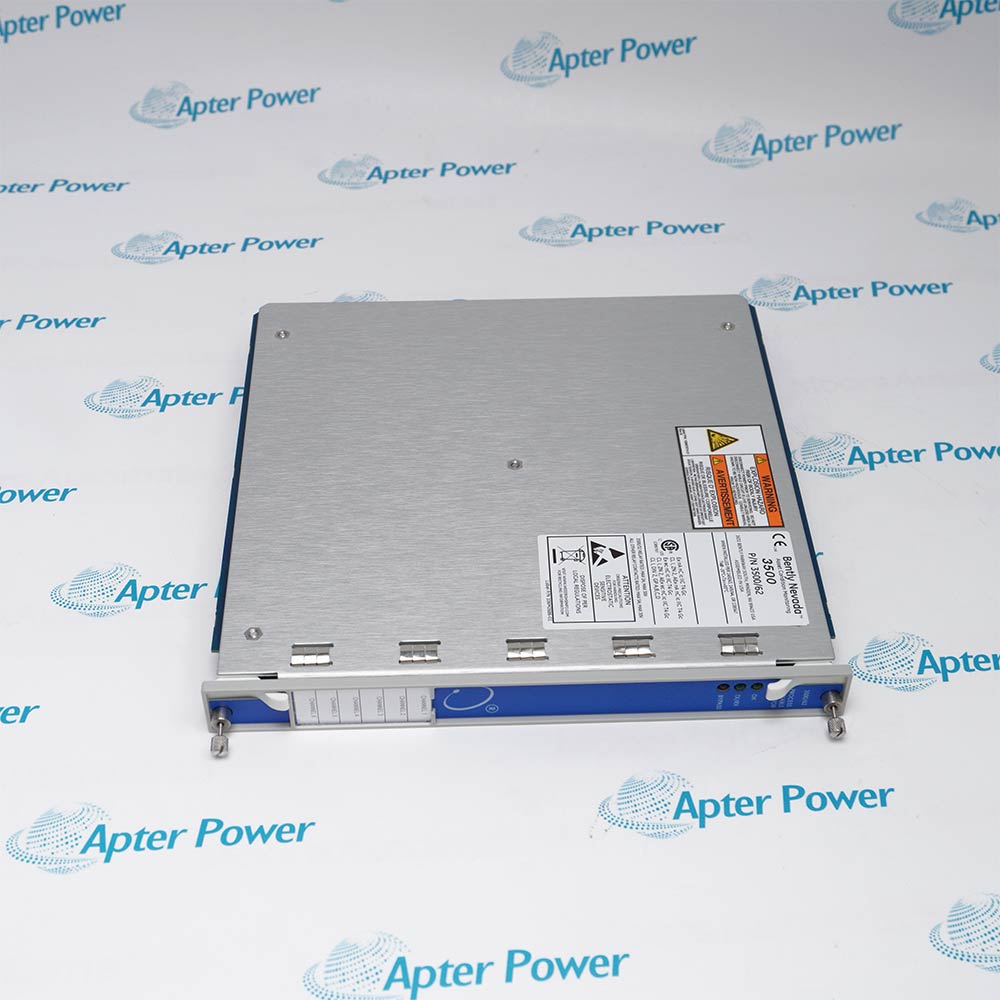
Include the complete Bently Nevada 3500/77M 143737-01 marking and any hardware revision on the item. Include the monitor/I/O pairing and cylinder/chamber wiring map.
-
Check the offered item before ordering
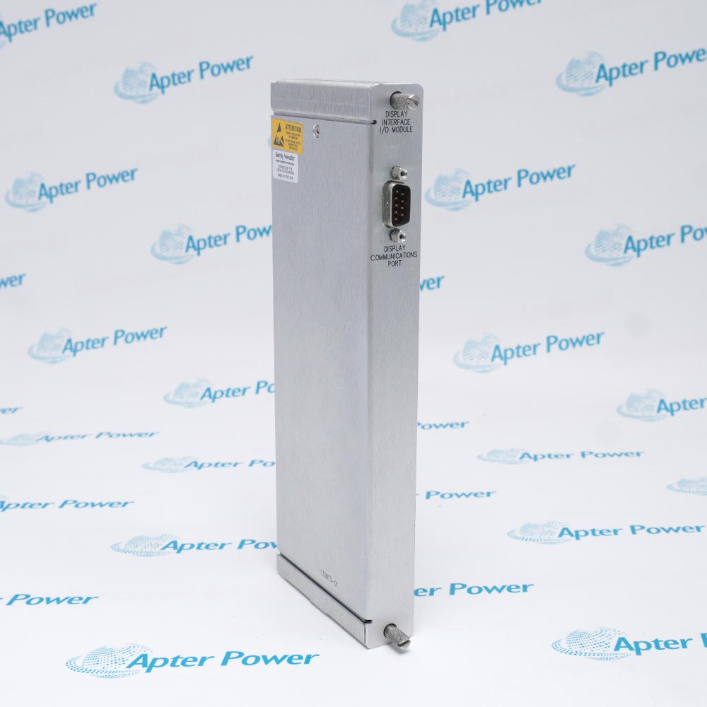
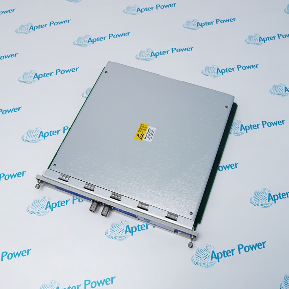
Request available label and connector photos. Have your maintenance team compare the offered 3500/77M 143737-01 with the installed equipment and applicable Bently Nevada documentation.
Technical specifications for 3500/77M 143737-01
-
Manufacturer:Bently Nevada
-
Product Category:Machinery Monitoring Systems
-
Spare Part Number:3500/77M 143737-01
-
Weight:0.85 kg
-
Tariff Code:8537101190
-
Input paths:1-4 pressure channels
-
Transducer signal:Approved positive-voltage pressure
-
Input impedance:50 kilohms
-
Termination:External
Information
- Bently Nevada 3500/77M 143737-01 preserves the connection between pressure transducers and their assigned compressor-monitor channels.
Transducer signal: Approved positive-voltage pressure
Input impedance: 50 kilohms
The pressure path uses each transducer calibration to relate its positive voltage to cylinder pressure. The five chamber variables are discharge, suction, maximum and minimum pressure plus compression ratio. Rod compression, rod tension and degree of rod reversal additionally require the configured mechanical parameters.
The system provides Alert setpoints for each active measured variable and Danger setpoints for two selected variables per channel. Diagnostic buffered outputs are inverted and offset by -2.265 VDC. These functions belong to the associated monitor; the external I/O board preserves the field connection and channel mapping.
3500/77M 143737-01 Official Technical Excerpt
The original technical excerpt for Bently Nevada 3500/77M 143737-01 covers pressure-monitor operation, I/O characteristics and exact spare roles. PDF · 6 pages.3500/77M 143737-01 Installation & Verification Guide
Apter Power installation and verification guide covering chamber mapping, calibration retention, termination recovery and alarm testing. PDF · 5 pages.
Application scope: Pressure and rod-load functions apply to the configured reciprocating-compressor system. Correct sensor scales and mechanical parameters are part of the measurement boundary.
Cylinder pressure supervision
Track suction, discharge, minimum and maximum chamber pressures.Compression assessment
Use calibrated chamber measurements to establish compression ratio.Rod-load evaluation
Combine pressure channels with the correct mechanical configuration.Protection-path maintenance
Restore field mapping and prove the assigned pressure alarms after replacement.
Record 3500/77M 143737-01 and each transducer-to-channel-to-chamber relationship. Identify the monitor and its matching internal or external termination arrangement.
Save pressure/voltage calibration points, configured ranges and the mechanical data used for rod-load calculations. Do not replace them with a generic sensor range.
Apply the approved compressor protection bypass and isolation procedure. Preserve the configured Alert/Danger assignments and relay-path relationship.
Use 143737-01 only for its external-termination I/O role and 176449-07 for the monitor role. Reconnect the correct field path without exchanging cylinder assignments.
Account for inversion and the -2.265 VDC offset when comparing diagnostic voltages. A direct raw-sensor comparison without that transformation is misleading.
Test the assigned Alert and Danger functions and review rod-load calculations against the configured mechanics. Do not release on a plausible pressure display alone.
Alternative Names
Technical notes
External field mapping: Retain the association between external terminals, transducers and cylinder chambers. A wiring swap can preserve plausible pressure values while assigning them to the wrong chamber.
Scale verification: Use a known pressure or equivalent approved voltage reference to prove the transducer scale through the I/O path and configured monitor.

FAQ View All FAQ
-
What termination arrangement identifies 3500/77M 143737-01?143737-01 is the cylinder-pressure I/O module with external terminations for approved pressure transducers.
-
Does 3500/77M 143737-01 perform cylinder calculations without a monitor?No. The I/O component forms the input connection path. The associated 3500/77M monitor performs conditioning, measured-variable calculations and alarm comparison.
-
What input impedance applies to the cylinder-pressure I/O used in 3500/77M 143737-01?The internal/external-termination cylinder-pressure I/O specification is 50 kilohms.
-
Can a generic vibration sensor be connected to 3500/77M 143737-01 as a pressure source?No. The 3500/77M pressure path requires approved positive-voltage pressure transducers with the corresponding pressure/voltage calibration.
-
Which wiring detail must be preserved when replacing 3500/77M 143737-01?Retain external termination routing and the channel-to-cylinder/chamber assignment. An internal-termination I/O selection has a different connection arrangement.
-
Why are two-point sensor calibration values important for 3500/77M 143737-01?The monitor uses the pressure transducer voltage/pressure relationship. The physical I/O connection does not establish the correct scale factor by itself.
-
Can the front buffered signal in a system using 3500/77M 143737-01 be treated as an unchanged sensor voltage?No. Cylinder-pressure monitor buffered outputs are inverted and offset by -2.265 VDC; account for this when interpreting diagnostic measurements.
-
What confirms correct channel recovery through 3500/77M 143737-01?Apply an approved pressure or voltage reference and verify the assigned monitor channel, configured scaling and alarm behavior. A sound connection alone does not establish correct cylinder mapping.
Supporting new and legacy automation
-
Please try to be as accurate as possible with your search.
-
We can quote you on 1000s of specialist parts, even if they are not listed on our website.
-
We can't find any results for “”.
You May Also Like
Product Browsing History
-
Whatsapp: +86 18030235313
Send us a message. -
sales13@apterpower.com
Complete our online form. -
+86 18030235313
Speak to our team in your native language.