Speak to a sourcing specialist
sales13@apterpower.com
Get a quick price for 330851-04-000-030-10-01-05
E-mail *
Mobile *
Company
Content *
Quantity *
Upload (gif, jpg, jpeg, png, bmp, doc, docx, xls, xlsx, ppt, pdf, csv)
For more information on how your data is processed and stored by Apterpower please read our privacy policy

What happens after you enquire

  • 1

    Requirement review

    We review the part number, quantity and delivery requirements and ask for any missing details.
  • 2

    Quotation and availability

    We confirm the proposed item, condition, availability, price and estimated lead time in the quotation.
  • 3

    Order confirmation and dispatch

    Once the quotation and purchasing details are agreed, your contact will coordinate the order and available dispatch information.

Technical specifications for 330851-04-000-030-10-01-05

  • Manufacturer:
    Bently Nevada
  • Product Category:
    Machinery Monitoring Systems
  • Spare Part Number:
    330851-04-000-030-10-01-05
  • Estimated shipping dimensions:
    2.8x2.8x115cm
  • Weight:
    0.34 kg
  • Tariff Code:
    8537101190
  • Counliy of origin:
    USA
  • Probe execution:
    Smooth 1.06 in diameter, side exit
  • Unthreaded length:
    0.0 in
  • Overall case length:
    3.0 in
  • Total probe length:
    1.0 m
  • Mechanical protection:
    Stainless-steel armor
  • Agency approval option:
    05
  • Linear range:
    12.7 mm
  • Linear range limits:
    0.63 to 13.33 mm
  • Approximate output range:
    -2.5 to -11.5 Vdc
  • Average scale factor:
    0.787 V/mm
  • Frequency response:
    0 to 2.7 kHz, +0/-3 dB
  • Minimum target diameter:
    61 mm
  • Probe DC resistance:
    6.2 +/-0.5 Ohm
  • Probe tip material:
    PEEK
  • Case material:
    AISI 304 stainless steel
  • Cable:
    75 Ohm PFA FluidLoc
  • Armor:
    AISI 302 stainless steel with PFA jacket
  • Minimum bend radius:
    25.4 mm
  • Operating temperature:
    -35 to +200 degC
  • Short-term probe temperature:
    +250 degC maximum for less than 24 h
  • Maximum connector torque:
    0.565 N m

Information

Overview Manuals Common Applications Product Precautions
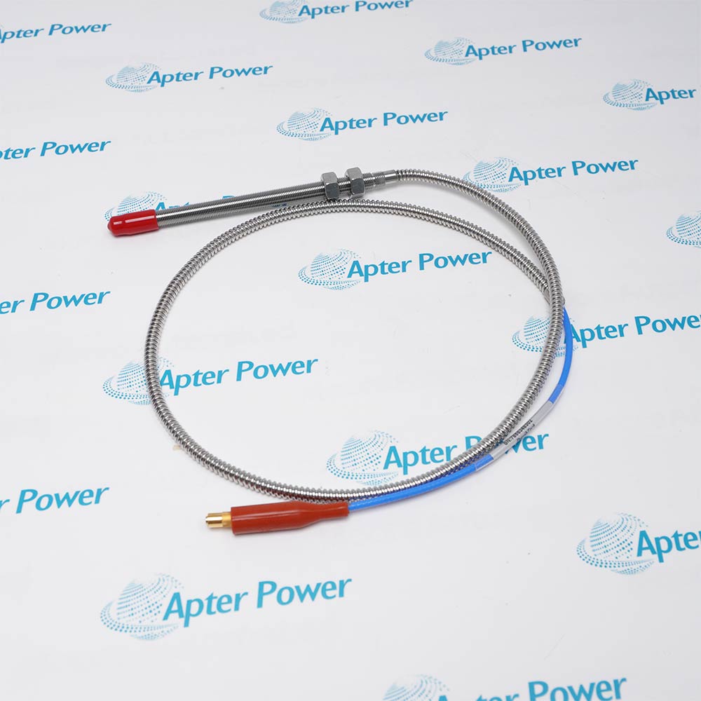
Bently Nevada 330851-04-000-030-10-01-05 is a smooth side-exit 3300 XL 25 mm proximity probe. It measures large shaft or rotor position changes for a matched transducer system and monitor channel.
  • Measures large-range shaft position with a 25 mm eddy-current probe
  • Provides a side-exit lead for the smooth probe body
  • Operates with a matched 3300 XL 25 mm extension cable and Proximitor Sensor
  • Supports applications requiring a 12.7 mm linear range

330851-04-000-030-10-01-05 installs with 3300 XL 25 mm Proximitor Sensor, matched 25 mm extension cable, 61 mm or larger steel target, compatible position-monitoring input in an engineered 3300 XL 25 mm Proximity Transducer System configuration.

The commissioning workflow covers installed-hardware matching, controlled start-up and functional verification for this 3300 xl 25 mm proximity probe.

Important Notice: Confirm the complete 330851-04-000-030-10-01-05 marking, installed-system configuration, field connections and controlled functional test before commissioning or replacement.


Apter Power 330851-04-000-030-10-01-05 Manuals and Guides
Apter Power 330851-04-000-030-10-01-05 Product Technical Reference PDFBently Nevada 330851-04-000-030-10-01-05 Official Manual PDF
The first document is an Apter Power model-specific technical reference. The second supports model-specific installation, configuration and engineering verification.
Steam-turbine differential expansionMeasures large-range shaft position with a 25 mm eddy-current probe
Large-shaft axial positionProvides a side-exit lead for the smooth probe body
Rotor movement observationOperates with a matched 3300 XL 25 mm extension cable and Proximitor Sensor
High-temperature proximity measurementSupports applications requiring a 12.7 mm linear range
Read the applicable Bently Nevada installation instructions before work. Verify 330851-04-000-030-10-01-05 and the installed 3300 XL 25 mm Proximity Transducer System configuration.
1Verify the full 330851-04-000-030-10-01-05 configuration before installation.
2Place the machine and connected position channel in the approved maintenance state.
3Protect the PEEK tip and smooth body from impact or clamp damage.
4Maintain the minimum bend radius in the armored side-exit lead.
5Use clean finger-tight connector assembly and do not exceed the connector torque limit.
6Match probe, extension cable and Proximitor Sensor as one 25 mm system.
7Set operating gap across the expected full mechanical travel.
8Prove direction, scale and alarm action before returning the measurement to service.

Technical notes

Support and align the smooth side-exit body so the 1 m FluidLoc lead is not loaded, then set gap within the 12.7 mm linear region and verify the matched 25 mm loop before commissioning.

FAQ View All FAQ

  • How should wiring or cabling for 330851-04-000-030-10-01-05 be recorded?
    Record conductor identity, shield termination, connector orientation, cable route and the as-found diagnostic state before disconnecting 330851-04-000-030-10-01-05.
  • What installation control is important for 330851-04-000-030-10-01-05?
    Use the model-specific mounting arrangement, protect mating surfaces and maintain the documented cable support and mechanical clearance for 330851-04-000-030-10-01-05.
  • How is 330851-04-000-030-10-01-05 checked during commissioning?
    Apply the approved controlled test for steam-turbine differential expansion, verify polarity or direction where applicable, and compare the measured response with the configured channel.
  • Can parameters from a similar model be used for 330851-04-000-030-10-01-05?
    No. Retain only values and configuration details that apply directly to the complete 330851-04-000-030-10-01-05 ordering code and installed system.
  • What maintenance evidence should be retained for 330851-04-000-030-10-01-05?
    Retain the full 330851-04-000-030-10-01-05 identity, as-left mounting and connections, continuity or bias checks, diagnostics and the final functional-test result.
  • What should be verified before returning 330851-04-000-030-10-01-05 to service?
    Confirm secure mounting, connector integrity, restored configuration, stable signal behavior and the intended response of the associated monitoring channel.
  • What must be matched before replacing 330851-04-000-030-10-01-05?
    Match the complete 330851-04-000-030-10-01-05 marking, 3300 xl 25 mm proximity probe, installed mounting or connector execution and the approved equipment record before removal.
  • Which system components should be checked with 330851-04-000-030-10-01-05?
    Confirm the installed 3300 XL 25 mm Proximitor Sensor, matched 25 mm extension cable and the assigned monitoring or connection point are the documented combination for 330851-04-000-030-10-01-05.
SPEAK TO OUR TEAM
Let’s find the right solution for you.
Send us the part number, quantity and delivery destination. Our team will help confirm availability and lead time.
  • Whatsapp: +86 18030235313

    Send us a message.
  • sales13@apterpower.com

    Complete our online form.
  • +86 18030235313

    Speak to our team in your native language.