-
Match the complete marking
Retain 330880-01-20-058-03-02 exactly, including every zero and suffix, when comparing the supplied item with the installed assembly.
-
Check the offered item before ordering
Request current 330880-01-20-058-03-02 item and connection photos; compare the mechanical interface, included parts and measuring-chain requirements.
Technical specifications for 330880-01-20-058-03-02
-
Manufacturer:Bently Nevada
-
Product Category:Machinery Monitoring Systems
-
Spare Part Number:330880-01-20-058-03-02
-
Weight:1.45 kg
-
Tariff Code:8537101190
-
Assembly family:PROXPAC XL; English ordering
-
Probe supply option:No probe supplied (01)
-
Sensor approval option:Proximitor sensor with Multiple Approvals (01)
-
Standoff adapter:2.0 in (20)
-
Probe penetration selection:5.8 in (058)
-
Fittings kit:One 3/4-14 NPT fitting; one 3/4-14 NPT to 1/2-14 NPT stainless-steel reducer; two plugs (03)
-
Mounting thread:3/4-14 NPT (02)
-
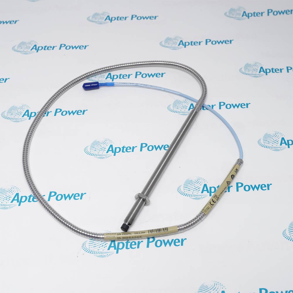
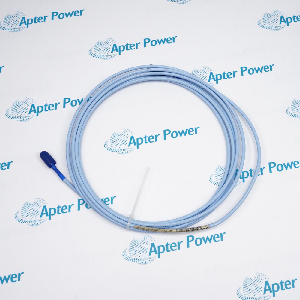
Required sensing input:Separately selected 3300 XL 8 mm probe with 1 m cable
-
Sensor supply without barriers:-17.5 to -26 V DC
-
Sensor supply with barriers:-23 to -26 V DC
-
Maximum sensor consumption:12 mA
-
Sensor output resistance:50 ohms
-
Field conductor size:0.2-1.5 mm2 (16-24 AWG)
-
Maximum field wiring:305 m between sensor and monitor
-
Housing material:UV-resistant, glass-reinforced conductive PPS
-
Enclosure rating:Type 4X / IP66
-
Housing and sensor operating range:-52 to +100 deg C
-
Storage temperature:-52 to +105 deg C
-
Retaining nut torque:29.5 N.m
-
Sleeve locknut torque:39.3 N.m
Information
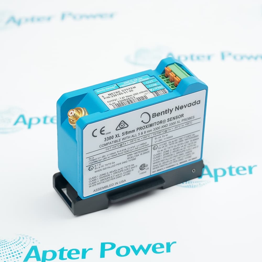
- At an external machine mounting point, Bently Nevada 330880-01-20-058-03-02 keeps the signal conditioner in the housing cover while the selected sleeve provides access for gap adjustment.
Connection: English NPT hardware
Conduit kit: Fitting, reducer and two plugs
Prepare the machine-side thread before assembling the mounting hardware. The standoff offsets the enclosure from the machine surface, while the sleeve provides the path to the sensing position.
Field-cable selection is separate from probe selection. Check conductor size, shielding and monitor wiring, and keep a service route available to the cover.
-
Bently Nevada 330880-01-20-058-03-02 technical reference
Original manufacturer excerpt - PDF, 7 pages. System architecture, operating limits, configuration and mounting information. -
Bently Nevada 330880-01-20-058-03-02 installation guide
Prepared by Apter Power - PDF, 5 pages. Pre-installation checks, wiring, adjustment, commissioning and fault isolation.
Platform applications: These applications describe external mounting and signal-conditioning arrangements. Match the mechanical options, complete measuring chain and approved installation before commissioning.
-
External sensor mounting
Place the integrated conditioner at the machine mounting point when a compatible proximity channel is assembled. -
Conduit adaptation
Use the supplied reducer where a 1/2-14 NPT conduit connection is required, while retaining the 3/4-14 NPT mounting arrangement. -
Accessible probe adjustment
Position the sleeve so a separately selected probe can be adjusted and serviced from outside the machine. -
Environmental protection
Use the sealed PPS enclosure in Type 4X or IP66 installations with protected connectors and properly closed entries.
Fit the correct 1 m 3300 XL 8 mm probe before functional testing; the ordered 01 configuration does not include it.
Use the required 3/4-14 NPT mounting arrangement with the selected standoff. Keep conduit reducers in their intended entry.
Do not pressurize the plastic enclosure. Apply the machine containment and isolation procedure before opening the assembly.
Use the specified conductor range and shielded wiring. Prevent conduit-borne moisture from entering the housing.
Apply the 29.5 N.m retaining-nut and 39.3 N.m sleeve-locknut torques without disturbing the final probe position.
Review sensor and probe approval markings, barrier requirements and the applicable drawing before applying negative DC power.
Alternative Names
Technical notes
Supply boundary: The 01 option supplies no probe. Select the compatible 1 m 3300 XL 8 mm probe and verify its sensor connection before commissioning.
Installation geometry: The 2.0 in standoff and 5.8 in penetration form a 7.8 in mid-setting reach. Use the machine drawing and the selected probe to set the final operating gap.
Technical reference: Bently Nevada PROXPAC XL Proximity Transducer Assembly, 178554 Rev. E.

FAQ View All FAQ
-
What is actually supplied under the 01 option of 330880-01-20-058-03-02?Option 01 selects a housing with a Proximitor sensor carrying the Multiple Approvals option, without a probe. A suitable 3300 XL 8 mm probe must be selected separately before the assembly can form a complete measuring channel.
-
How do the 20 and 058 selections position 330880-01-20-058-03-02?The English-ordering standoff is 2.0 inches and the selected penetration is 5.8 inches. Their sum is a 7.8 inch mid-setting reach; the threaded sleeve permits adjustment around that position. Final probe gap is established at the machine.
-
Does 330880-01-20-058-03-02 include an adapter for a half-inch conduit connection?The 03 fittings kit includes one 3/4-14 NPT fitting, a stainless-steel reducer from 3/4-14 NPT to 1/2-14 NPT, and two plugs. The reducer adapts the conduit entry; it does not change the assembly mounting thread.
-
Why is the 02 mounting option needed with the standoff on 330880-01-20-058-03-02?The 02 mounting option provides the 3/4-14 NPT interface required when a standoff adapter is ordered. The standoff and the machine-side sleeve connection must use the specified assembly arrangement.
-
Can the enclosure rating of 330880-01-20-058-03-02 be used as a pressure-vessel rating?Type 4X and IP66 describe enclosure protection. The plastic housing is not designed to resist internal or external pressure, so the installation must safely contain and control process fluids if the transducer seals leak.
-
Which wiring route connects 330880-01-20-058-03-02 to the monitoring instrument?Three-conductor shielded field wiring carries supply, common and output between the integrated sensor and the monitor. Use conductors of 0.2 to 1.5 mm2 and keep the sensor-to-monitor run within the 305 m limit.
-
When does the sleeve-support rule affect an installation using 330880-01-20-058-03-02?Additional support near the probe is required when the combined B and C dimensions exceed 12.0 inches. The selected 7.8 inch combination is below that threshold; the machine mounting and vibration environment still need to be assessed.
-
What must be checked before applying power to 330880-01-20-058-03-02 through barriers?Confirm the selected probe, sensor markings and approved circuit first. The sensor requires -23 to -26 V DC when barriers are used, compared with -17.5 to -26 V DC without barriers; a more positive supply can reduce measuring range.
Supporting new and legacy automation
-
Please try to be as accurate as possible with your search.
-
We can quote you on 1000s of specialist parts, even if they are not listed on our website.
-
We can't find any results for “”.
You May Also Like
Product Browsing History
-
Whatsapp: +86 18030235313
Send us a message. -
sales13@apterpower.com
Complete our online form. -
+86 18030235313
Speak to our team in your native language.