-
Match the complete marking
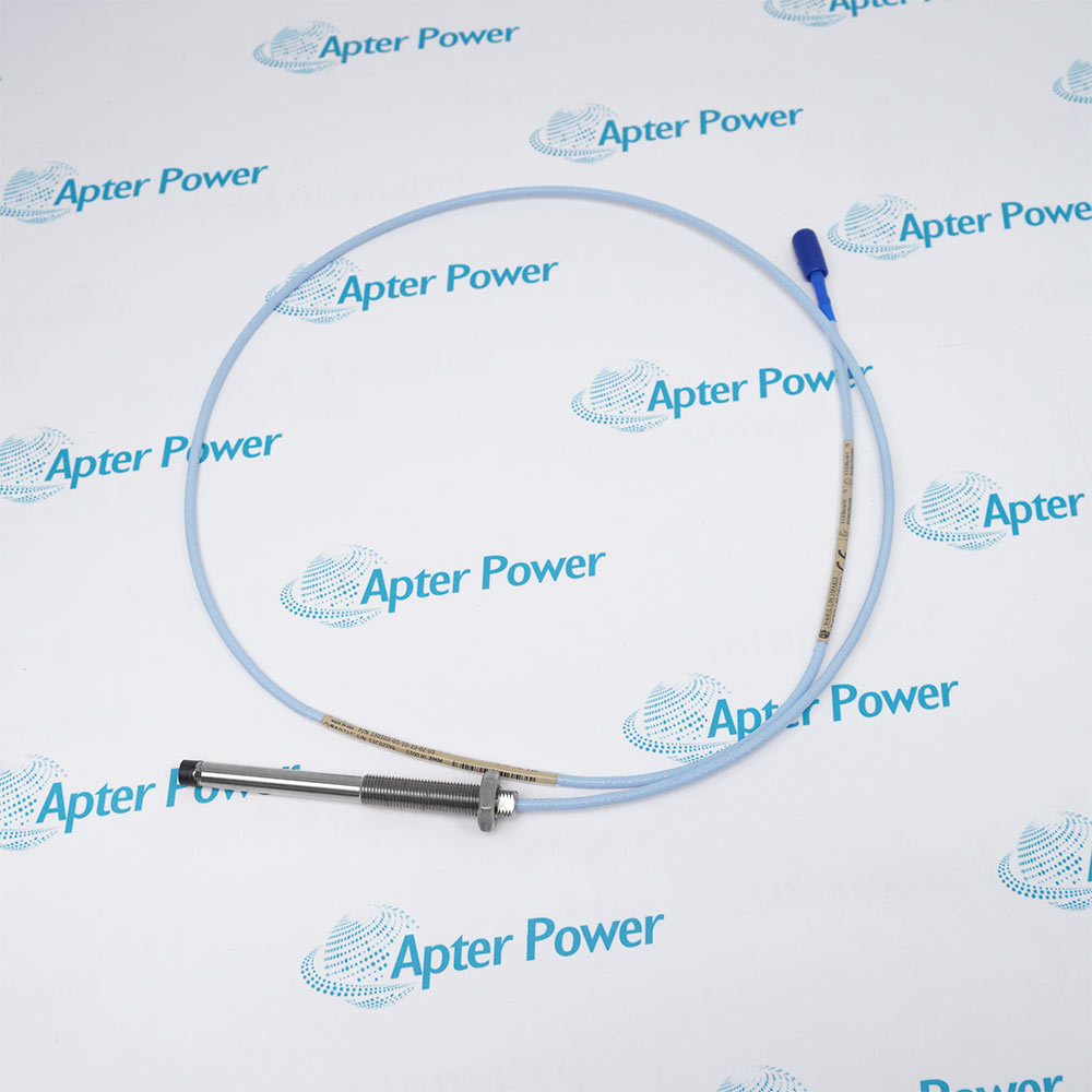
Include 330801-28-20-050-03-02 and any serial or assembly marking visible on the offered unit. Keep the complete 28 / 20 / 050 / 03 / 02 option sequence on the enquiry and quotation.
-
Check the offered item before ordering
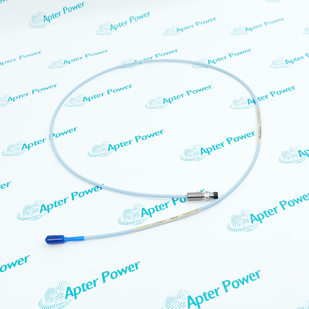
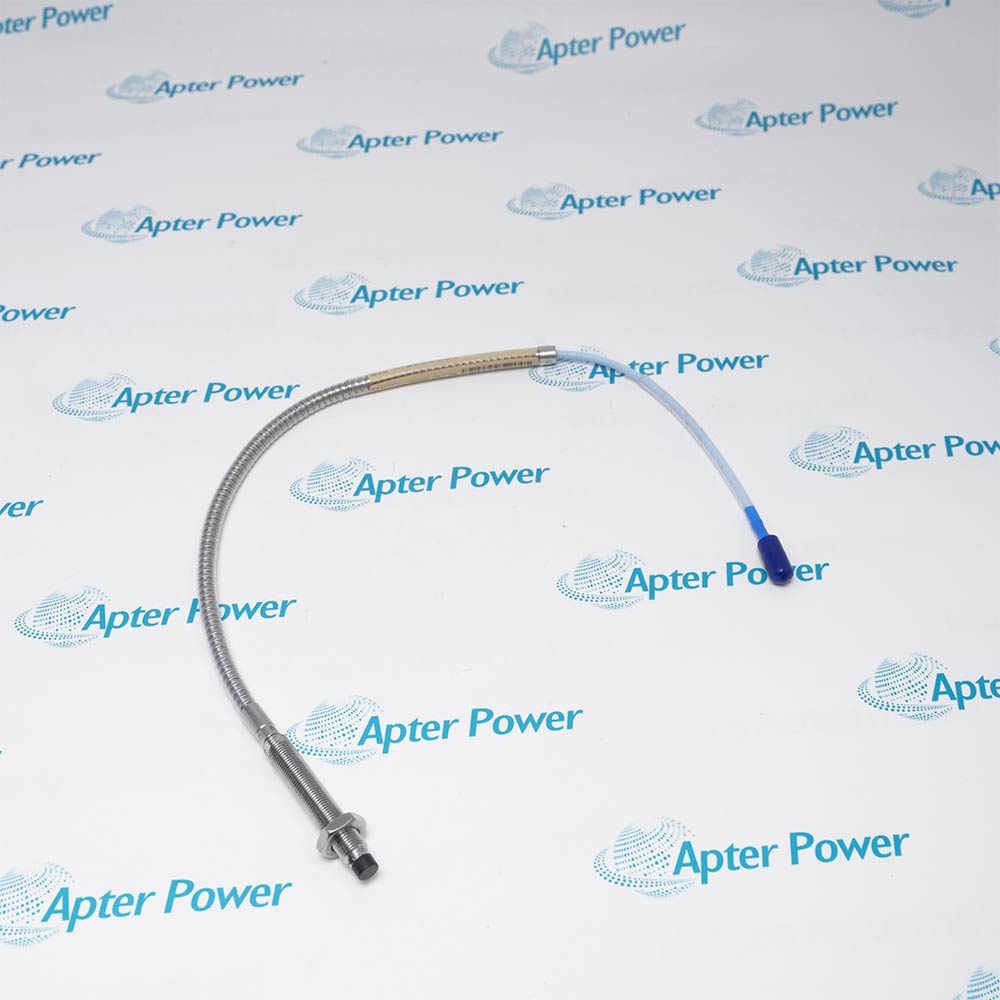
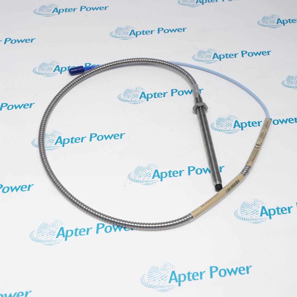
Request current label, housing-cover sensor, probe connection and fittings photos. Have your maintenance team compare the offered 330801-28-20-050-03-02 configuration with the installed machine mounting and monitoring circuit.
Technical specifications for 330801-28-20-050-03-02
-
Manufacturer:Bently Nevada
-
Product Category:Machinery Monitoring Systems
-
Spare Part Number:330801-28-20-050-03-02
-
Estimated shipping dimensions:27.8x9.5x9.2cm
-
Weight:1.5 kg
-
Tariff Code:8537101190
-
Counliy of origin:USA
-
Assembly family:PROXPAC metric
-
Probe option:3300 XL 8 mm; multiple approvals (28)
-
Standoff adapter:200 mm (20)
-
Probe penetration:50 mm (050)
-
Fittings kit:One M20 fitting; two plugs (03)
-
Mounting thread:3/4-14 NPT (02)
-
Supply without barriers:-17.5 to -26 V DC
-
Supply with barriers:-23 to -26 V DC
-
Maximum current consumption:12 mA
-
Output resistance:50 ohms
-
Nominal probe DC resistance:7.58 +/- 0.5 ohms
-
Linear measuring span:2.0 mm (80 mils)
-
Recommended probe gap:1.27 mm (50 mils)
-
Incremental scale factor:7.87 mV/um (200 mV/mil); +/-5.5% typical
-
Frequency response:0-8 kHz; +0/-3 dB at 50 mils gap; up to 305 m field wiring
-
Maximum field wiring length:305 m
-
Field cable:Three-conductor twisted shielded cable
-
Probe cable:1 m; 75 ohm triaxial; FEP insulation
-
Probe connector:Gold-plated brass ClickLoc; connector protector
-
Housing protection:Type 4X / IP66
-
Housing material:UV-resistant glass-reinforced conductive PPS
-
Probe operating temperature:-51 to +177 deg C
-
Housing operating temperature:-34 to +100 deg C
-
Housing storage temperature:-34 to +105 deg C
-
Retaining nut torque:29.5 N.m
-
Probe sleeve locknut torque:39.3 N.m
Information
- Bently Nevada 330801-28-20-050-03-02 lets technicians adjust and access the sensing probe from outside the machine while retaining local signal conditioning at the mounting point.
Probe option: 3300 XL 8 mm with multiple approvals
Fittings: One M20 fitting and two plugs
The 200 mm standoff and 50 mm penetration options establish the mounting geometry. Check the machine bore around the sensing tip before fixing the sleeve position.
Field wiring connects the housing-cover electronics to the monitor. Route the conduit to prevent liquid from entering the enclosure and preserve access for maintenance.
-
Bently Nevada 330801-28-20-050-03-02 technical reference
Original manufacturer excerpt - PDF, 8 pages. System description, electrical limits, metric ordering options and mounting information. -
Bently Nevada 330801-28-20-050-03-02 installation guide
Prepared by Apter Power - PDF, 5 pages. Pre-installation checks, wiring, adjustment, commissioning and fault isolation.
Installation contexts: The applications below describe sensing and service arrangements; assess the installed machine and hazardous-area circuit before commissioning.
-
Radial vibration measurement
Observe shaft motion with a proximity probe, preserving target clearance and sufficient spacing from adjacent sensing tips to control cross-talk. -
Axial position measurement
Use a conductive target and a correctly set gap for position measurement. Check target geometry and adjacent-probe separation before release. -
Local signal conditioning
Keep the probe connection within the PROXPAC housing and carry power, common and signal between the integrated sensor and monitoring instrument. -
External probe maintenance
Access the probe sleeve outside the machine. Record its location before withdrawal, then re-establish the operating gap after reinstallation.
Equalize pressure before opening the housing or removing the probe sleeve. Provide containment for process fluid if the sensing assembly leaks.
For the 050 option, assess the machine counterbore and nearby metal to reduce side-view and rear-view effects on the sensing tip.
Tighten the probe sleeve locknut to 39.3 N.m and the retaining nut to 29.5 N.m. Maintain the selected gap while securing the assembly.
Seal unused entries with the supplied plugs and route conduit so that liquid cannot travel into the enclosure. Protect the probe connector.
Use the applicable negative DC supply range, identify VT, COM and OUT correctly, and ground the field-cable shield at one point at the monitor.
Recheck the probe gap and scale factor after components are replaced or disturbed. Treat an erratic or changed response as a reason for verification.
Alternative Names
Technical notes
Installation relationship: The selected B plus C reach is 250 mm. Check the C050 counterbore clearance and use the machine drawing and probe gap-setting procedure to establish the installed position.
Protection: Type 4X and IP66 apply to the enclosure. The plastic housing does not resist internal or external pressure; intrinsically safe installations require the complete approved circuit and applicable control drawing.
Technical reference: Bently Nevada PROXPAC Proximity Transducer Assembly, 141621-01 Rev. F; Installation Manual 131236-01 Rev. F.

FAQ View All FAQ
-
Does 330801-28-20-050-03-02 need an extension cable between its probe and Proximitor sensor?The PROXPAC assembly places the Proximitor sensor in the housing cover, so the probe connects locally without an intervening extension cable. Field wiring carries the signal to the monitoring instrument.
-
How much standoff does option 20 provide on 330801-28-20-050-03-02?The metric standoff code 20 selects a 200 mm adapter. Check this offset together with the penetration length when locating the machine mounting point.
-
Why should the machine bore be checked for the 050 penetration option on 330801-28-20-050-03-02?The 050 option selects 50 mm penetration, within the short-penetration range where a counterbore may be needed to reduce probe side-view or rear-view effects.
-
Which conduit fittings come with the 03 option of 330801-28-20-050-03-02?The metric fittings kit 03 contains one M20 fitting and two plugs. Match the conduit entry to this kit and seal unused housing openings.
-
What mounting connection must accept the 02 option of 330801-28-20-050-03-02?The 02 mounting option uses a 3/4-14 NPT connection. This mounting thread is required when the standoff adapter is fitted.
-
Can 330801-28-20-050-03-02 use the same supply range with and without barriers?Without barriers the supply range is -17.5 to -26 V DC at a maximum of 12 mA; with barriers it is -23 to -26 V DC. A supply more positive than -23.5 V DC may reduce the linear range.
-
Under what conditions does 330801-28-20-050-03-02 provide its 0-8 kHz response?The +0/-3 dB response applies at a 50 mils probe gap with up to 305 m of field wiring. Cable length and barriers must be considered when assessing high-frequency signal rolloff.
-
When should the scale factor of 330801-28-20-050-03-02 be verified again?Verify the scale factor after components have been replaced or disturbed, when performance changes or becomes erratic, or when calibration is in doubt. The check uses a digital multimeter, power supply, spindle micrometer and 10 kilohm resistor.
Supporting new and legacy automation
-
Please try to be as accurate as possible with your search.
-
We can quote you on 1000s of specialist parts, even if they are not listed on our website.
-
We can't find any results for “”.
You May Also Like
Product Browsing History
-
Whatsapp: +86 18030235313
Send us a message. -
sales13@apterpower.com
Complete our online form. -
+86 18030235313
Speak to our team in your native language.