Product image is representative; revision or series may vary. Contact us to request a specific version.
Product Describe:
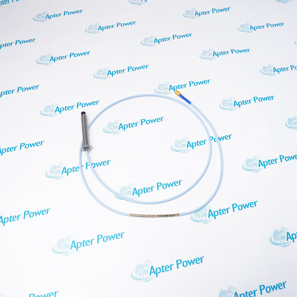
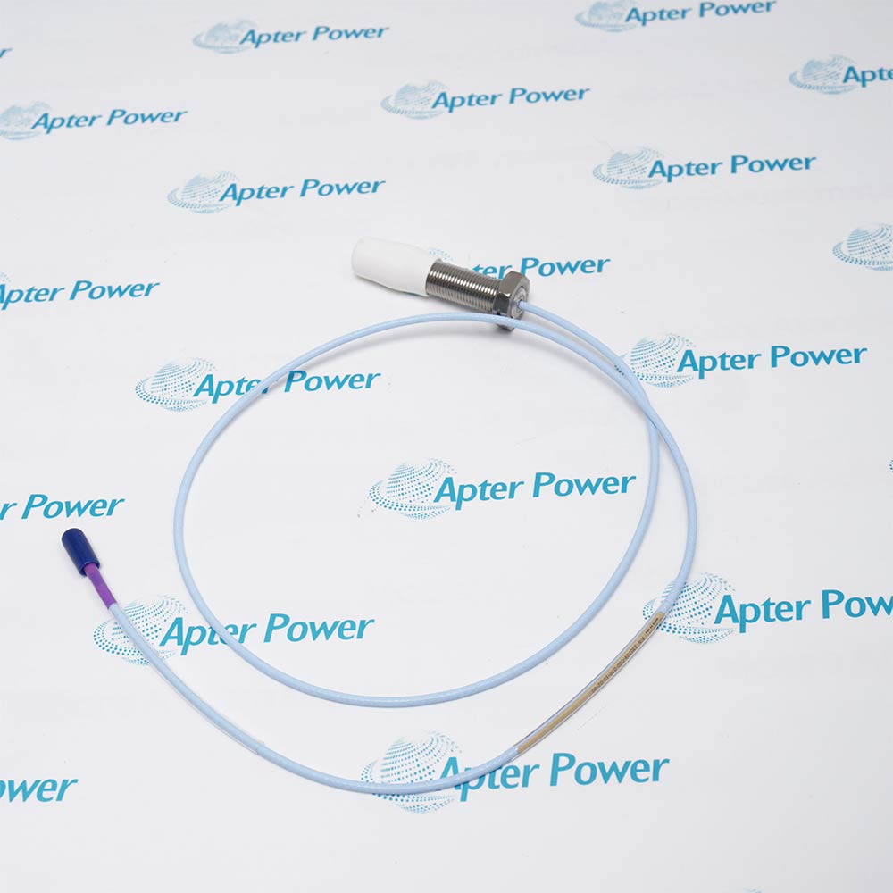
Bently Nevada 330703-000-040-10-11-00 is a 3300 XL 11 mm proximity probe with a 0 mm unthreaded length, 40 mm case, 1.0 m total length and armored FluidLoc cable.
Built for the 3300 XL 11 mm measurement chain, Bently Nevada 330703-000-040-10-11-00 carries the probe signal through an armored FluidLoc lead while preserving the calibrated electrical length.
Uses the 3300 XL 11 mm eddy-current transducer family.
Provides a 40 mm case with no unthreaded section.
Supplies a 1.0 m probe assembly for the matched system.
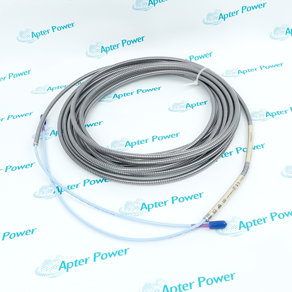
Uses an armored FluidLoc lead with miniature ClickLoc termination.
330703-000-040-10-11-00 must remain matched to its documented system interface, mating hardware and controlled configuration.
Important Notice: Match the complete 330703-000-040-10-11-00 marking and documented interfaces before installation, then verify the intended technical response.
The first document covers the product function, system role and technical selection. The installation guide covers identification, connection checks, commissioning and the acceptance record.

Radial vibration measurement
Supports non-contact shaft-vibration measurement on large rotating machinery.
Axial position measurement
Measures controlled shaft position within the calibrated transducer range.
Differential expansion systems
Provides the sensing element for matched machinery-protection loops.
Oil-exposed probe routing
Uses the FluidLoc cable option to reduce leakage through the cable interior.
Before installing Bently Nevada 330703-000-040-10-11-00, confirm the documented system, interfaces and controlled configuration.
1
Match all five ordering-code groups before removal.
2
Use only the documented 3300 XL 11 mm extension cable and Proximitor sensor.
3
Do not shorten, splice or repair the calibrated probe lead.
4
Protect the ClickLoc connector from contamination during handling.
5
Route the armored FluidLoc lead without exceeding its bend limit.
6
Set the probe gap inside the calibrated linear region.
7
Verify polarity and proportional target response after connection.
8
Restore the assigned monitor channel and protection logic only after functional testing.
Technical notes
Match the complete 330703-000-040-10-11-00 marking and documented interfaces before installation, then verify the intended technical response.