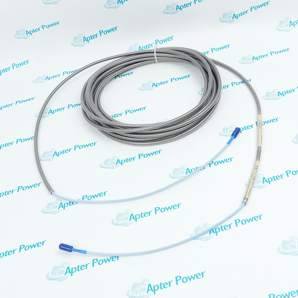
-
Match the complete marking
3/8-16 unc mounting adaptor and no requested agency approval. Match the Velomitor input type, 100 mV/in/s scaling, connector polarity and 3/8-16 UNC adaptor. A mechanically similar accelerometer is not a direct velocity-output substitute.
-
Check the offered item before ordering
The sensor operates with a compatible Velomitor monitor input and a two-conductor cable. The selected 07 adaptor is part of this configuration; additional cable assemblies are separate unless itemized. Retain the current channel settings for verification.
Technical specifications for 330500-07-00
-
Manufacturer:Bently Nevada
-
Product Category:Machinery Monitoring Systems
-
Spare Part Number:330500-07-00
-
Weight:0.16 kg
-
Tariff Code:8537101190
-
Sensitivity:3.94 mV/mm/s (100 mV/in/s) ±5%
-
Frequency response, ±3 dB:4.5 Hz to 5 kHz
-
Frequency response, ±0.9 dB:6.0 Hz to 2.5 kHz
-
Velocity range:1270 mm/s peak
-
Amplitude linearity:±2% to 152 mm/s peak
-
Transverse sensitivity:<5%
-
Mounted resonant frequency:>12 kHz
-
Output bias voltage:-12 ±3 V DC referenced to Pin A
-
Dynamic output impedance:<2400 ohms
-
Noise floor:0.004 mm/s RMS nominal; 4.5 Hz to 5 kHz
-
Operating temperature:-55 to +121 °C
-
Temperature sensitivity:-14% to +7.5% typical over operating range
-
Shock survivability:5,000 g peak maximum
-
Humidity:To 100%, non-submerged
-
Case material:316L stainless steel
-
Grounding:Case isolated
-
Connector:Two-pin MIL-C-5015
-
Mounting adaptor:3/8-16 UNC
-
Polarity:Motion toward connector: Pin A positive relative to Pin B
-
Cable-specific length limit:305 m with cable 02173006
Information
- Bently Nevada 330500-07-00 measures vibration transmitted from the rotor through bearings and the machine casing. Its solid-state sensing design permits vertical, horizontal or angled installation without moving-coil wear.
Response bands: 4.5 Hz to 5 kHz at ±3 dB; 6 Hz to 2.5 kHz at ±0.9 dB
Connection: Two-pin MIL-C-5015, case isolated
The 07 option supplies a 3/8-16 UNC mounting adaptor. A two-pin MIL-C-5015 connector carries the signal from the electrically isolated case; motion toward the connector makes Pin A positive relative to Pin B. The -12 ±3 V DC output bias is referenced to Pin A, and the receiving channel must retain the intended polarity and velocity scaling.
The hermetically sealed 316L stainless-steel sensor operates from -55 to +121 °C and has no moving-coil mechanism to wear. A rigid connection to the bearing housing or casing is still necessary to transmit the vibration of interest. Further integration of its velocity output to displacement can amplify electrical noise and produce inaccurate displacement readings.
330500-07-00 Official Velomitor Datasheet Excerpt
Original velocity response, polarity, environmental limits, cable references and drawings. PDF · 7 pages.330500-07-00 Installation & Verification Guide
Casing location, adaptor fitting, two-pin connection, velocity testing and noise assessment. PDF · 5 pages.
Application scope: A casing signal can support machine assessment only when the mounting point transmits the relevant vibration. It is not automatically a substitute for direct rotor measurement.
Rolling-element bearing housings
Trend absolute casing velocity where the bearing housing transmits the vibration of interest.Machine casing vibration
Monitor unbalance or misalignment effects at a suitable rigid casing location, with the mechanical transfer path considered.Structural velocity monitoring
Measure structural vibration within the qualified bandwidth and amplitude envelope.Angled sensor installations
Maintain a chosen measurement direction on horizontal, vertical or inclined mounting surfaces.
Avoid flexible covers or surfaces that attenuate machine vibration.
Use the specified 3/8-16 UNC machine-side thread.
Track Pin A and Pin B through the connector and receiving input.
Assess electrical noise before using integrated displacement readings.
Keep the sensor within -55 to +121 °C and inspect cable suitability separately.
Confirm bias and a known velocity response before restoring configured protection.
Alternative Names
Technical notes
Configuration: 3/8-16 unc mounting adaptor and no requested agency approval.
Integration: The sensor operates with a compatible Velomitor monitor input and a two-conductor cable. The selected 07 adaptor is part of this configuration; additional cable assemblies are separate unless itemized.
Acceptance: Confirm bias and a known velocity response before restoring configured protection.
Technical reference: Bently Nevada 330500 Velomitor Piezo-velocity Sensor, 141632 Rev. V.

FAQ View All FAQ
-
Does 330500-07-00 measure shaft-relative motion?It measures absolute bearing-housing, casing or structural vibration velocity. It does not directly measure shaft motion relative to a nearby probe.
-
What is the difference between the two frequency bands of 330500-07-00?The wider 4.5 Hz to 5 kHz band allows ±3 dB variation; the 6 Hz to 2.5 kHz band has the tighter ±0.9 dB response limit.
-
Which polarity should a motion toward the connector produce on 330500-07-00?Pin A becomes positive with respect to Pin B when the sensor case moves toward the connector. Preserve the same pin convention through the cable and monitor input.
-
Why can a displacement trend derived from 330500-07-00 become noisy?Integrating velocity amplifies the influence of low-frequency electrical interference and transducer-circuit noise. Review the integration bandwidth and signal quality before accepting displacement data.
-
Can 330500-07-00 be installed on a horizontal bearing housing?Yes. The solid-state sensor can operate vertically, horizontally or at another angle. The mounting surface still needs a rigid vibration path.
-
Is the maximum velocity range also the linearity test range of 330500-07-00?No. The velocity range is 1270 mm/s peak, while ±2% amplitude linearity is specified to 152 mm/s peak.
-
Does a 305 m cable limit apply to every 330500-07-00 cable assembly?No. That limit is stated for cable 02173006. Evaluate the selected assembly, cable capacitance and signal conditions instead of treating it as a universal cable allowance.
-
How does the 07 adaptor affect replacement of 330500-07-00?It supplies a 3/8-16 UNC mounting adaptor. Confirm the machine-side thread and contact surface before fitting a replacement; other adaptor options use different threads.
Supporting new and legacy automation
-
Please try to be as accurate as possible with your search.
-
We can quote you on 1000s of specialist parts, even if they are not listed on our website.
-
We can't find any results for “”.
You May Also Like
Product Browsing History
-
Whatsapp: +86 18030235313
Send us a message. -
sales13@apterpower.com
Complete our online form. -
+86 18030235313
Speak to our team in your native language.