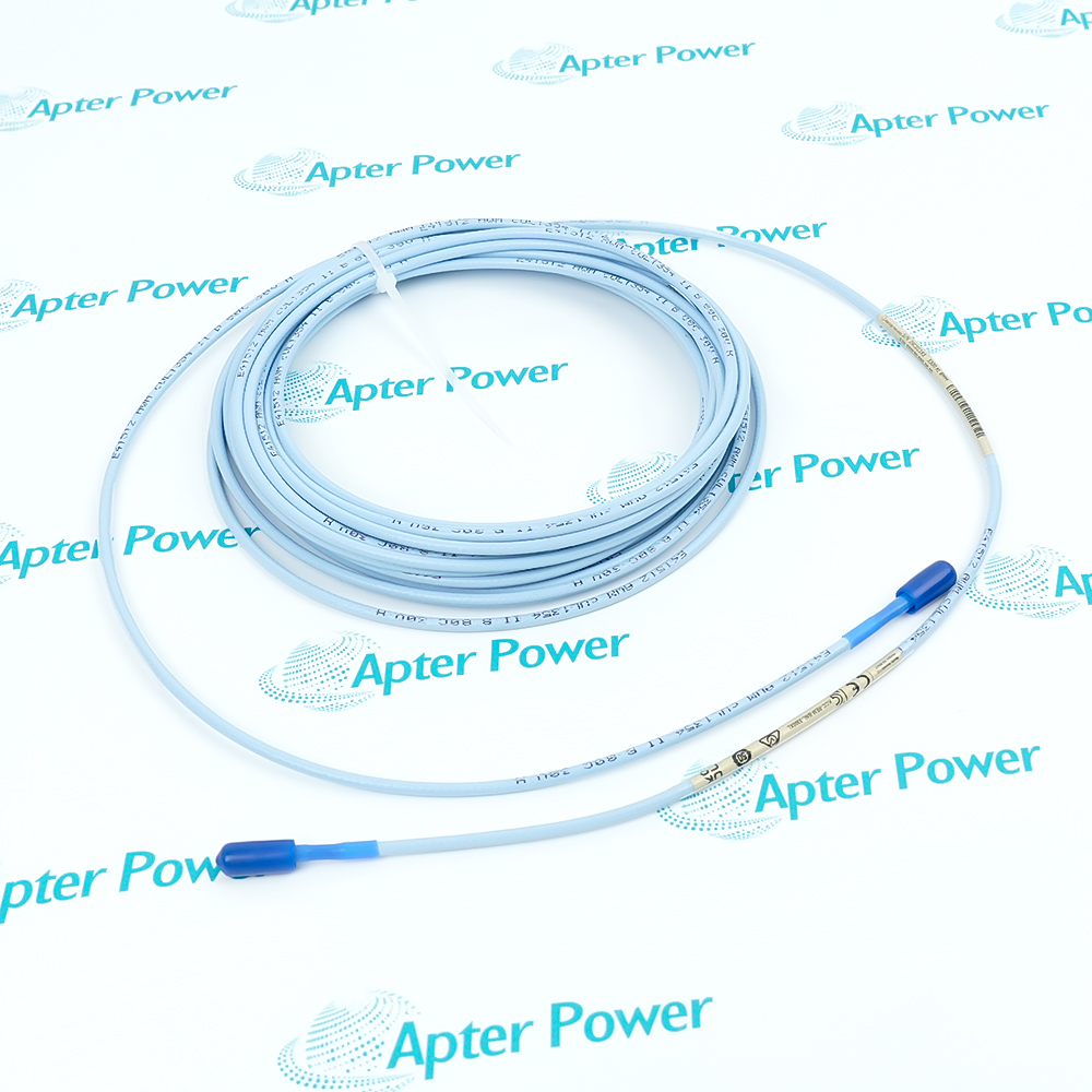
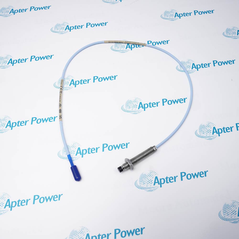
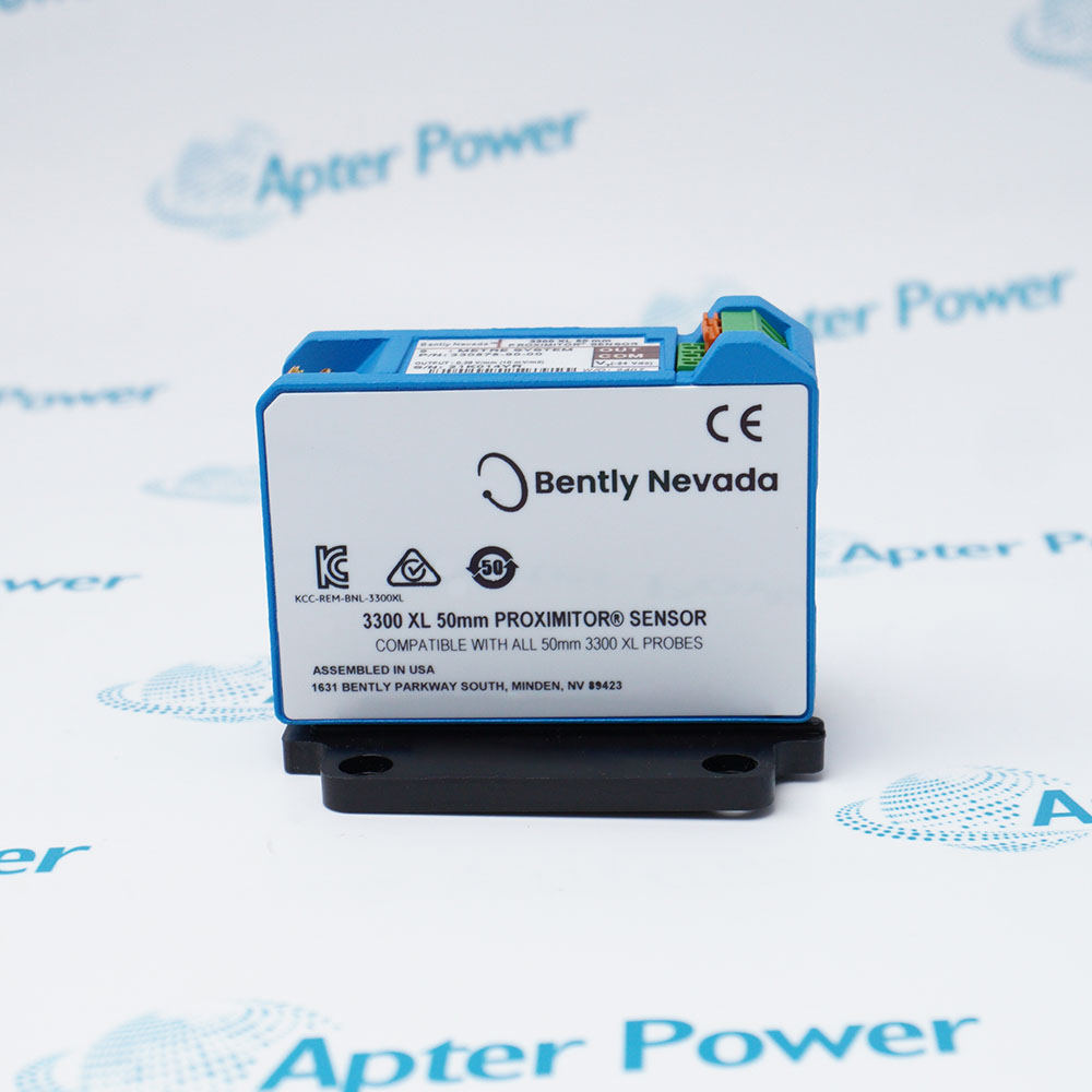
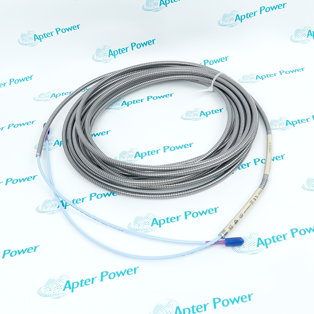
Product image is representative; revision or series may vary. Contact us to request a specific version.
Product Describe:
Bently Nevada 330106-00-04-10-02-00 is an 8 mm reverse-mount eddy-current proximity probe for non-contact shaft vibration, position, Keyphasor reference and speed measurements in a matched 3300 XL measurement chain.
In a machinery-monitoring channel, Bently Nevada 330106-00-04-10-02-00 forms the sensing end of the probe, extension-cable and Proximitor arrangement while retaining its complete supplied marking.
330106-00-04-10-02-00
330106
3300 XL 8 mm
Reverse mount
Retain the exact host position, connections and configuration record. Complete controlled diagnostics and a functional test before service release.
Important Notice: Confirm 330106-00-04-10-02-00, every companion marking and the recorded acceptance result before replacement.
The first PDF is an unchanged technical excerpt from the applicable manufacturer publication; the second provides a separate installation, verification and handover workflow.

Shaft-vibration measurement
Observes relative shaft motion on fluid-film bearing machines through the matched transducer chain.
Axial-position monitoring
Tracks static shaft position when the installed probe geometry and target remain within the approved gap range.
Keyphasor reference service
Produces a once-per-turn reference when the probe is positioned at the configured shaft event.
Speed observation
Supports rotational-speed measurement through the receiving monitor and configured target feature.
Read the applicable product and site instructions before work. Verify 330106-00-04-10-02-00, the installed host and every connected interface before isolation or replacement.
1
Confirm the complete 330106-00-04-10-02-00 marking and M10 x 1 reverse-mount position before work.
2
Match the installed extension cable and Proximitor Sensor to the retained total system length.
3
Record probe gap, mounting depth, cable route, connector condition and shield treatment before removal.
4
Protect the 8 mm tip, cable and ClickLoc connection from impact, contamination and strain.
5
Use the approved target material and mounting torque without forcing the threaded case.
6
Restore the probe cable and extension-cable connection without sharp bends or unsupported tension.
7
Set the operating gap with the receiving monitor in the controlled maintenance state.
8
Verify static gap, dynamic response, alarm path and speed or phase reference before service release.
Alternative Names
Technical notes
Match 330106-00-04-10-02-00 to the complete installed identity, host position and companion hardware. Preserve every connection and setting; release only after diagnostics and a controlled test of non-contact shaft position and vibration sensing.