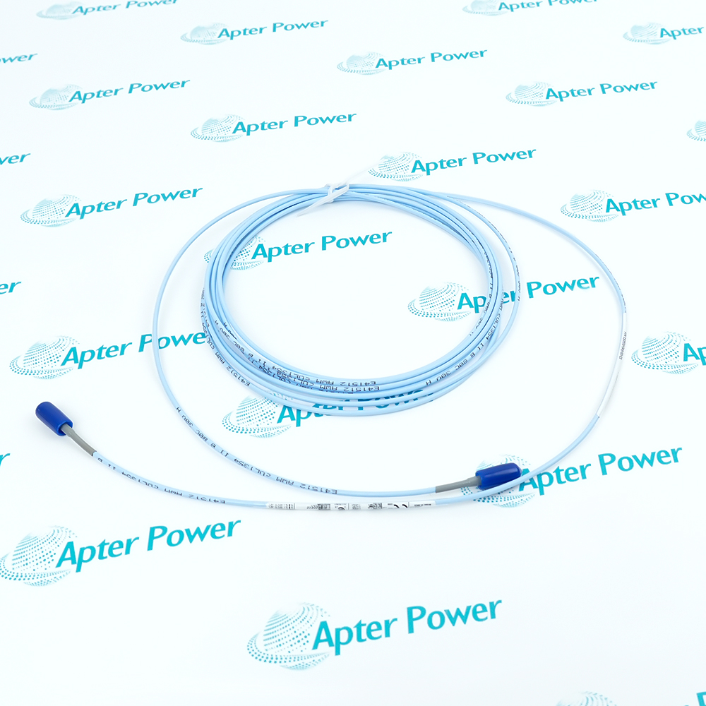
Technical specifications for 330104-00-04-50-02-00
-
Manufacturer:Bently Nevada
-
Product Category:Machinery Monitoring Systems
-
Spare Part Number:330104-00-04-50-02-00
-
Estimated shipping dimensions:33x33x3cm
-
Weight:0.58 kg
-
Tariff Code:8537101190
-
Counliy of origin:USA
-
Probe thread:M10 x 1
-
Cable armor:Stainless steel with FEP jacket
-
Unthreaded length:0 mm
-
Overall case length:40 mm
-
Total probe length:5.0 m
-
Connector:Miniature coaxial ClickLoc
-
Connector protector:Not included
-
Agency approval option:00
-
Probe tip material:Polyphenylene sulfide (PPS)
-
Probe case material:AISI 303 or 304 stainless steel
-
Cable impedance:75 ohm triaxial
-
Cable insulation:FEP
-
Minimum cable bend radius:25.4 mm (1.0 in)
-
Maximum probe-to-lead tensile strength:330 N (75 lbf)
-
Maximum lead-to-extension tensile strength:270 N (60 lbf)
-
Connector material:Gold-plated brass or beryllium copper
-
Recommended connector torque:Finger tight
-
Maximum connector torque:0.565 N m (5 in lbf)
-
Standard probe temperature:-52 to +177 degC
Information
- Uses an armored five-metre probe lead
- Fits an M10 x 1 metric mounting thread
- Protects the probe cable with stainless-steel armor
- Provides the sensing element for static position and dynamic vibration
330104-00-04-50-02-00 is installed with 3300 XL 8 mm Proximitor Sensor, compatible 3300 XL extension cable when required, AISI 4140 steel target, Bently Nevada monitor channel.
Engineered applications include Radial shaft-vibration measurement, Axial shaft-position monitoring, Machine centerline observation, Keyphasor reference sensing.
Important Notice: Confirm the M10 x 1 bracket thread and 40 mm case clearance, do not exceed the documented thread engagement, protect the armored lead from side load, and set the probe gap only after the matched system is assembled.
Apter Power 330104-00-04-50-02-00 Manuals and Guides
Apter Power 330104-00-04-50-02-00 Product Technical Reference PDF330104-00-04-50-02-00 Engineering Installation and Verification WorkbookThe first document presents model-specific technical identity and engineering data. The second provides a separate installation, connection and commissioning workflow.
Radial shaft-vibration measurement
330104-00-04-50-02-00 supports this documented 3300 XL 8 mm Proximity Transducer System engineering task.
Axial shaft-position monitoring
330104-00-04-50-02-00 supports this documented 3300 XL 8 mm Proximity Transducer System engineering task.
Machine centerline observation
330104-00-04-50-02-00 supports this documented 3300 XL 8 mm Proximity Transducer System engineering task.
Keyphasor reference sensing
330104-00-04-50-02-00 supports this documented 3300 XL 8 mm Proximity Transducer System engineering task.
Verify the complete 330104-00-04-50-02-00 marking and its documented 3300 XL 8 mm Proximity Transducer System position before field work.
Place the monitored machine and associated protection channel in the approved maintenance state before disconnecting 3300 XL 8 mm metric armored proximity probe.
Protect every exposed connector and cable end from oil, moisture, dirt and impact while 330104-00-04-50-02-00 is open.
Record probe, extension-cable and Proximitor Sensor identities so the calibrated system length is preserved.
Route 330104-00-04-50-02-00 without sharp bends, crushing, abrasion or tensile loading at either coaxial termination.
Clean and finger-tighten each ClickLoc connection; never transfer connector torque or wiring practice from a different transducer family.
Set the static gap only after mechanical mounting and the complete matched loop have been confirmed.
Verify polarity, dynamic response and alarm action before returning the machinery-protection channel to service.

Technical notes
FAQ View All FAQ
-
What connector checks are required for 330104-00-04-50-02-00?Inspect both mating surfaces for contamination or damage, align the ClickLoc connector correctly and tighten it finger-tight until the locking action is complete.
-
How should 330104-00-04-50-02-00 be routed in a machinery enclosure?Maintain the documented bend radius, provide mechanical support and keep the cable away from sharp edges, hot surfaces and locations that can impose tensile load.
-
What must be recorded before replacing 330104-00-04-50-02-00?Record the full catalog marking, mounting position, companion component numbers, cable route, monitor channel, static gap and as-found polarity.
-
How is the channel recommissioned after installing 330104-00-04-50-02-00?Restore the matched loop, verify supply and bias voltage, prove movement through the expected linear region and test the configured alarm or trip response under controlled conditions.
-
Can 330104-00-04-50-02-00 be mixed with another probe family?Use only combinations explicitly permitted by the 3300 XL 8 mm Proximity Transducer System documentation; connector fit alone does not establish electrical calibration or interchangeability.
-
What maintenance condition should trigger inspection of 330104-00-04-50-02-00?Inspect the assembly after cable impact, connector contamination, abnormal bias voltage, unstable vibration, loss of linear response or any work that changes the probe mounting.
-
Which Bently Nevada transducer system uses 330104-00-04-50-02-00?330104-00-04-50-02-00 belongs to the 3300 XL 8 mm Proximity Transducer System and must be combined only with the probe, extension cable and Proximitor Sensor arrangement documented for that system.
-
How should engineers confirm the system length for 330104-00-04-50-02-00?Add the installed probe lead and extension-cable lengths, then compare the total with the matching Proximitor Sensor length before energizing the channel.
Supporting new and legacy automation
-
Please try to be as accurate as possible with your search.
-
We can quote you on 1000s of specialist parts, even if they are not listed on our website.
-
We can't find any results for “”.
You May Also Like
Product Browsing History
-
Whatsapp: +86 18030235313
Send us a message. -
sales13@apterpower.com
Complete our online form. -
+86 18030235313
Speak to our team in your native language.