-
Match the complete marking
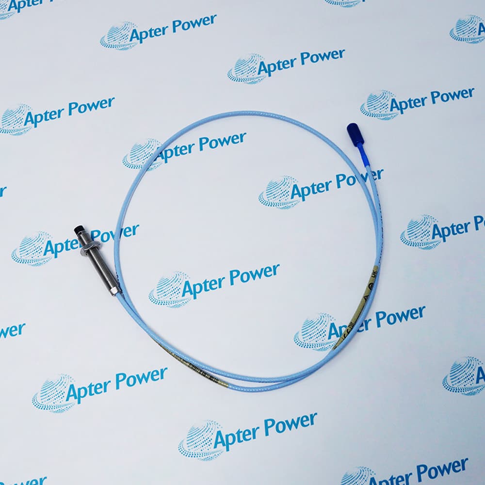
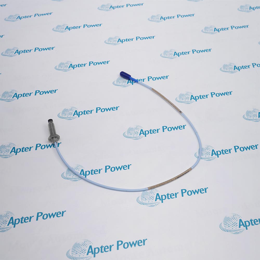
Match the complete 330103-00-06-90-02-00 marking, case geometry, cable length and connector arrangement to the installed measurement position.
-
Check the offered item before ordering
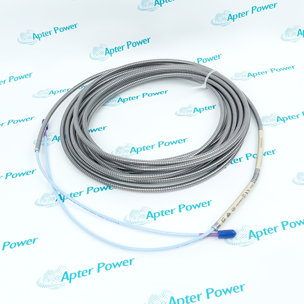
Request available label and connector photos. Have your maintenance team compare the offered 330103-00-06-90-02-00 with the installed equipment and applicable Bently Nevada documentation.
Technical specifications for 330103-00-06-90-02-00
-
Manufacturer:Bently Nevada
-
Product Category:Machinery Monitoring Systems
-
Spare Part Number:330103-00-06-90-02-00
-
Weight:0.2 kg
-
Tariff Code:8537101190
-
Measurement principle:Non-contact eddy current
-
Mounting thread:M10 x 1
-
Total probe length:9.0 m
-
Cable impedance:75 ohm triaxial
-
Cable insulation:FEP, standard cable
-
Probe tip material:PPS
-
Probe case material:AISI 303 or 304 stainless steel
-
Nominal probe DC resistance:9.87 ± 0.50 ohm, center to outer conductor
-
Standard probe temperature:-52°C to +177°C
-
Matched-system nominal scale factor:7.87 V/mm
-
Matched-system linear range:2 mm under specified calibration conditions
Information
- Bently Nevada 330103-00-06-90-02-00 carries the probe signal through an integral 9.0 m cable, allowing a matched 9 m Proximitor Sensor to condition the signal without adding a separate extension section.
Electrical length: 9.0 m total probe cable
Connection: ClickLoc connector without factory protector
The 9.0 m probe connects to the corresponding 9 m Proximitor Sensor without an added extension cable. An extra extension would alter the calibrated electrical length.
A standard 9 m system provides a nominal 7.87 V/mm incremental scale factor with ±6.5% interchangeability error over the specified linear range at 0°C to +45°C. Its straight-line deviation is less than ±0.038 mm under those conditions. Target material and geometry, component temperatures and the signal-conditioning configuration remain part of the measurement specification.
330103-00-06-90-02-00 Official Datasheet Excerpt
The original technical excerpt covers 3300 XL 8 mm probe construction, electrical behavior and system limits relevant to 330103-00-06-90-02-00. PDF · 9 pages.330103-00-06-90-02-00 Installation & Verification Guide
Apter Power installation workflow for the 9.0 m probe, selected case interface, connector protection and commissioning checks. PDF · 5 pages.
Application scope: The applications below concern the complete calibrated measurement chain. Target material, physical clearance and monitor configuration determine suitability for each machine position.
Shaft vibration
Use the 9.0 m probe path to acquire non-contact shaft motion within the calibrated system range.Static shaft position
Condition the probe gap signal with the matched Proximitor Sensor for a monitor configured for position.Machine mounting
The 60 mm case and 0 mm unthreaded section define the available reach and support interface for this selection.Measurement-chain renewal
Use the 9.87 ± 0.50 ohm probe resistance as one isolated continuity check before a full gap-response verification.
Limit M10 x 1 thread engagement to 15 mm. Case length does not increase this limit.
The 9.0 m probe connects to the corresponding 9 m Proximitor Sensor without an added extension cable. An extra extension would alter the calibrated electrical length.
The ClickLoc connector is supplied without a factory-installed connector protector. Prevent contact with surrounding conductive surfaces.
Apply the probe temperature limit separately from the lower Proximitor operating-temperature limit.
Verify target material and geometry. AISI 4140 steel is the reference calibration target.
Check actual DC gap and response to controlled displacement before restoring protection.
Alternative Names
Technical notes
System relationship: The 9.0 m probe connects to the corresponding 9 m Proximitor Sensor without an added extension cable. An extra extension would alter the calibrated electrical length.
Connection protection: The standard ClickLoc connection is supplied without a factory-installed connector protector. Keep connector insulation, mechanical support and pressure containment separate.
Calibration boundary: A standard 9 m system provides a nominal 7.87 V/mm incremental scale factor with ±6.5% interchangeability error over the specified linear range at 0°C to +45°C. Its straight-line deviation is less than ±0.038 mm under those conditions.

FAQ View All FAQ
-
Is a separate extension cable needed with 330103-00-06-90-02-00?Its integral 9.0 m probe cable already supplies the 9 m electrical length. Pair it with the appropriate 9 m Proximitor Sensor; adding an extension would change that length.
-
What scale-factor tolerance applies to a standard 9 m system using 330103-00-06-90-02-00?The nominal incremental scale factor is 7.87 V/mm with ±6.5% including interchangeability error, measured in 0.25 mm increments over the linear range at 0°C to +45°C under the specified calibration conditions.
-
Which straight-line deviation limit belongs to the 330103-00-06-90-02-00 9 m configuration?For a standard 9 m system with components at 0°C to +45°C, deviation from the best-fit straight line is less than ±0.038 mm. The tighter standard 1 m or 5 m limit must not be substituted.
-
How does the long probe cable change the resistance check for 330103-00-06-90-02-00?The 9.0 m probe has a nominal center-to-outer conductor resistance of 9.87 ± 0.50 ohm. A 1 m probe resistance limit is not the acceptance value for this cable.
-
Can excess cable from 330103-00-06-90-02-00 be cut away at the sensor cabinet?No. Retain the calibrated 9.0 m length and route it without damaging the cable. Cutting it changes the system configuration rather than merely tidying the installation.
-
Does 330103-00-06-90-02-00 use the same calibration as a 5 m Proximitor Sensor?No. The selected 9.0 m probe requires the matching electrical-length calibration. Mechanical connector compatibility alone does not establish a calibrated system.
-
What voltage span corresponds to the linear measurement range with 330103-00-06-90-02-00?The matched system has a nominal 2 mm linear range, approximately 0.25 to 2.3 mm from the target, corresponding to about -1 to -17 VDC under the stated calibration conditions.
-
How are cable loss and field-wire response distinguished when installing 330103-00-06-90-02-00?The 9 m probe cable is part of the calibrated transducer system. Wiring downstream of the Proximitor is a separate circuit; long field wiring can reduce high-frequency response and must be assessed independently.
Supporting new and legacy automation
-
Please try to be as accurate as possible with your search.
-
We can quote you on 1000s of specialist parts, even if they are not listed on our website.
-
We can't find any results for “”.
You May Also Like
Product Browsing History
-
Whatsapp: +86 18030235313
Send us a message. -
sales13@apterpower.com
Complete our online form. -
+86 18030235313
Speak to our team in your native language.