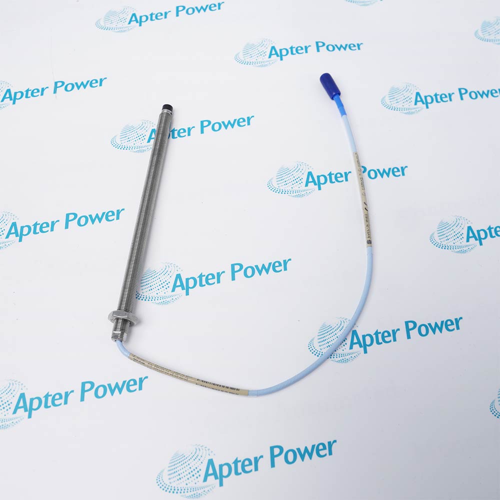
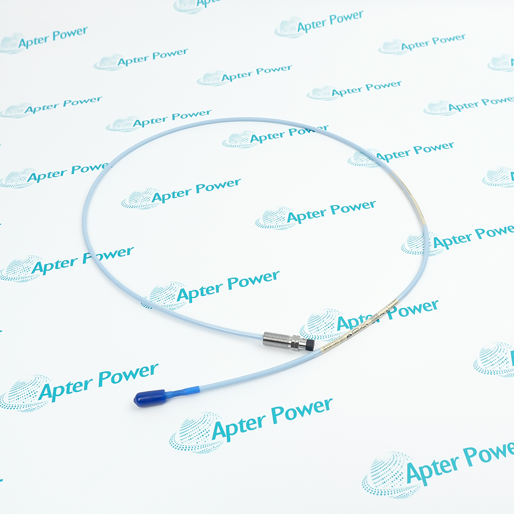
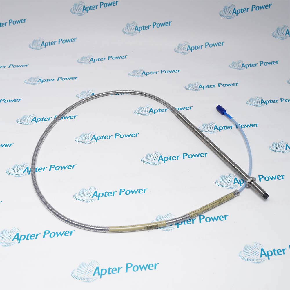
Product image is representative; revision or series may vary. Contact us to request a specific version.
Product Describe:
Bently Nevada 3300/50 is a 3300 XL 50 mm proximity transducer system for differential expansion and rotor expansion measurement on large steam-turbine generators, with a maximum linear range of 27.9 mm (1100 mil).
At a turbine supervisory instrumentation boundary, Bently Nevada 3300/50 combines a large-diameter probe, extension cable and 50 mm Proximitor Sensor to measure rotor-to-stator expansion over an extended range.
3300/50
3300 XL 50 mm Proximity Transducer System
50 mm probe, extension cable and 50 mm Proximitor Sensor
Differential expansion or rotor expansion
Retain the exact host position, connections and configuration record. Complete controlled diagnostics and a functional test before service release.
Important Notice: Confirm 3300/50, every companion marking and the recorded acceptance result before replacement.
The first PDF is an unchanged technical excerpt from the applicable manufacturer publication; the second provides a separate installation, verification and handover workflow.

Steam-turbine differential expansion
Measures the growth difference between the turbine rotor and casing through the approved collar or ramp arrangement.
Rotor expansion measurement
Tracks axial rotor growth over the extended 27.9 mm linear range.
Complementary-input arrangement
Uses opposing transducers when the required differential-expansion range exceeds one single-input span.
Legacy 50 mm system renewal
Provides a physical replacement path for a standard 7200 50 mm measurement position when the complete transducer chain is changed.
Read the applicable product and site instructions before work. Verify 3300/50, the installed host and every connected interface before isolation or replacement.
1
Confirm the 3300/50 system identity, probe style, thread, target geometry and measurement direction before work.
2
Record the collar or ramp dimensions, probe positions, gap values and indicated expansion before removal.
3
Replace the probe, extension cable and Proximitor Sensor as one matched 3300 XL 50 mm chain.
4
Keep high-temperature FluidLoc cable, ClickLoc connectors and seals clean, dry and mechanically supported.
5
Verify single-input or complementary-input geometry against the required differential-expansion range.
6
Set probe gaps by moving the transducer through the approved sliding-bracket travel where fitted.
7
Check scale factor and linearity across the controlled mechanical travel before enabling protection logic.
8
Confirm channel direction, alarms, trip logic and recorded rotor-to-casing movement before service release.
Technical notes
Match 3300/50 to the complete installed identity, host position and companion hardware. Preserve every connection and setting; release only after diagnostics and a controlled test of extended-range differential and rotor expansion measurement.