Get Parts Quote
Name
Company *
Phone *
Email *
Address
City
State / Province / Region
Zipcode
Country
Quantity *
Part Number *
Manufacturer
Preferred Condition
Additional Information
Cancel

24701-34-05-00-041-03-02

Proximity Probe Housing Assembly
In Stock
Ships by Tuesday, September 22
Fast Shipping Available

Product Describe:

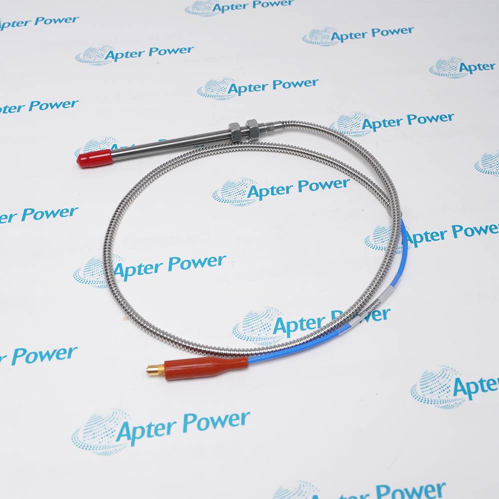
Bently Nevada 24701-34-05-00-041-03-02 is a stainless-steel proximity probe housing assembly. It positions and protects a 3300 XL 8 mm probe at an external machine mounting point.

Ask our team:

Get a quick price for: 24701-34-05-00-041-03-02
Quantity*
Upload (gif, jpg, jpeg, png, bmp, doc, docx, xls, xlsx, ppt, pdf, csv)
For more information on how your data is processed and stored by Apterpower please read our privacy policy.

Technical specifications for 24701-34-05-00-041-03-02

Technical specifications for 24701-34-05-00-041-03-02

  • Manufacturer:
    Bently Nevada
  • Product Category:
    Machinery Monitoring System
  • Spare Part Number:
    24701-34-05-00-041-03-02
  • Estimated shipping dimensions:
    26x7.8x7.8cm
  • Weight:
    2.14 kg
  • Tariff Code:
    8537101190
  • Counliy of origin:
    USA
  • Housing material:
    Stainless steel
  • Probe family option:
    3300 XL 8 mm
  • Probe cable length:
    20 in (0.5 m)
  • Standoff adaptor:
    None
  • Probe penetration:
    4.1 in (104 mm approximately)
  • Housing body material:
    303 stainless steel
  • Housing sleeve material:
    304 stainless steel
  • Mounting thread:
    3/4-14 NPT
  • Conduit accessories:
    3/4-14 NPT plug; 3/4-to-1/2 NPT reducer; cable seal grip
  • Adjustment range:
    13 mm
  • Environmental enclosure:
    CSA Type 4
  • Industry conformance:
    API 670

Information

Information

Overview Manuals Common Applications Product Precautions
Bently Nevada 24701-34-05-00-041-03-02 is a stainless-steel proximity probe housing assembly. It positions and protects a 3300 XL 8 mm probe at an external machine mounting point.
  • Protects and positions an externally mounted proximity probe
  • Provides controlled insertion adjustment at the machine case
  • Routes the probe lead through a sealed conduit entry
  • Supports service access without opening the machine casing

24701-34-05-00-041-03-02 installs with 3300 XL 8 mm proximity probe, machine case 3/4-14 NPT port, sealed conduit system, matched proximity transducer loop in an engineered 21000 and 24701 Probe Housing Assemblies configuration.

The commissioning workflow covers installed-hardware matching, controlled start-up and functional verification for this proximity probe housing assembly.

Important Notice: Confirm the complete 24701-34-05-00-041-03-02 marking, installed-system configuration, field connections and controlled functional test before commissioning or replacement.

Apter Power 24701-34-05-00-041-03-02 Manuals and Guides
Apter Power 24701-34-05-00-041-03-02 Product Technical Reference PDFBently Nevada 24701-34-05-00-041-03-02 Official Manual PDF
The first document is an Apter Power model-specific technical reference. The second supports model-specific installation, configuration and engineering verification.
Turbine bearing-case probe mountingProtects and positions an externally mounted proximity probe
Compressor shaft-vibration probe accessProvides controlled insertion adjustment at the machine case
External axial-position probe housingRoutes the probe lead through a sealed conduit entry
API 670 machinery installationSupports service access without opening the machine casing
Read the applicable Bently Nevada installation instructions before work. Verify 24701-34-05-00-041-03-02 and the installed 21000 and 24701 Probe Housing Assemblies configuration.
1Verify the complete 24701-34-05-00-041-03-02 configuration before assembly.
2Place the machine and probe channel in the approved maintenance state.
3Inspect the NPT machine port, housing threads and sealing surfaces.
4Establish penetration without allowing the probe tip to contact the shaft.
5Secure the sleeve and cable seal grip after the final adjustment.
6Maintain conduit drainage and enclosure sealing appropriate to the installation.
7Confirm probe cable routing and matched-system length before connection.
8Record final penetration, gap voltage and controlled channel-test results.

Technical notes

Technical notes

Set 24701-34-05-00-041-03-02 penetration and sleeve position from the machine drawing, seal the conduit accessories and confirm full shaft clearance before final probe gapping.

FAQS

  • What installation control is important for 24701-34-05-00-041-03-02?
    Use the model-specific mounting arrangement, protect mating surfaces and maintain the documented cable support and mechanical clearance for 24701-34-05-00-041-03-02.
  • How is 24701-34-05-00-041-03-02 checked during commissioning?
    Apply the approved controlled test for turbine bearing-case probe mounting, verify polarity or direction where applicable, and compare the measured response with the configured channel.
  • Can parameters from a similar model be used for 24701-34-05-00-041-03-02?
    No. Retain only values and configuration details that apply directly to the complete 24701-34-05-00-041-03-02 ordering code and installed system.
  • What maintenance evidence should be retained for 24701-34-05-00-041-03-02?
    Retain the full 24701-34-05-00-041-03-02 identity, as-left mounting and connections, continuity or bias checks, diagnostics and the final functional-test result.
  • What should be verified before returning 24701-34-05-00-041-03-02 to service?
    Confirm secure mounting, connector integrity, restored configuration, stable signal behavior and the intended response of the associated monitoring channel.
  • What must be matched before replacing 24701-34-05-00-041-03-02?
    Match the complete 24701-34-05-00-041-03-02 marking, proximity probe housing assembly, installed mounting or connector execution and the approved equipment record before removal.
  • Which system components should be checked with 24701-34-05-00-041-03-02?
    Confirm the installed 3300 XL 8 mm proximity probe, machine case 3/4-14 NPT port and the assigned monitoring or connection point are the documented combination for 24701-34-05-00-041-03-02.
  • How should wiring or cabling for 24701-34-05-00-041-03-02 be recorded?
    Record conductor identity, shield termination, connector orientation, cable route and the as-found diagnostic state before disconnecting 24701-34-05-00-041-03-02.
Trusted by 5,000+ plants worldwide | Backed by our vast inventory of top-tier control parts, modules and cards, fast shipments are dispatched to cover your urgent needs. ABOUT US >>
Disclaimer: We are not an authorized distributor or distributor of the product manufacturer of this website, The product may have older date codes or be an older series than that available direct from the factory or authorized dealers. Because our company is not an authorized distributor of this product, the Original Manufacturer`s warranty does not apply.While many DCS PLC products will have firmware already installed, Our company makes no representation as to whether a DSC PLC product will or will not have firmware and, if it does have firmware, whether the firmware is the revision level that you need for your application. Our company also makes no representations as to your ability or right to download or otherwise obtain firmware for the product from our company, its distributors, or any other source. Our company also makes no representations as to your right to install any such firmware on the product. Our company will not obtain or supply firmware on your behalf. It is your obligation to comply with the terms of any End-User License Agreement or similar document related to obtaining or installing firmware.

We’re Here When You Need Us

From product insights to customer service needs, our experienced service team will focus on getting you what you need quickly

Enquire

Complete our online form.

Call Us

Speak to one of our team.

Live Chat

Send us a message.