Get Parts Quote
Name
Company *
Phone *
Email *
Address
City
State / Province / Region
Zipcode
Country
Quantity *
Part Number *
Manufacturer
Preferred Condition
Additional Information
Cancel

200152-XX-XX-XX MOD: 323357-10-03-10

200152 accelerometer interface standard cable
In Stock
Ships by Sunday, September 13
Fast Shipping Available

Product Describe:

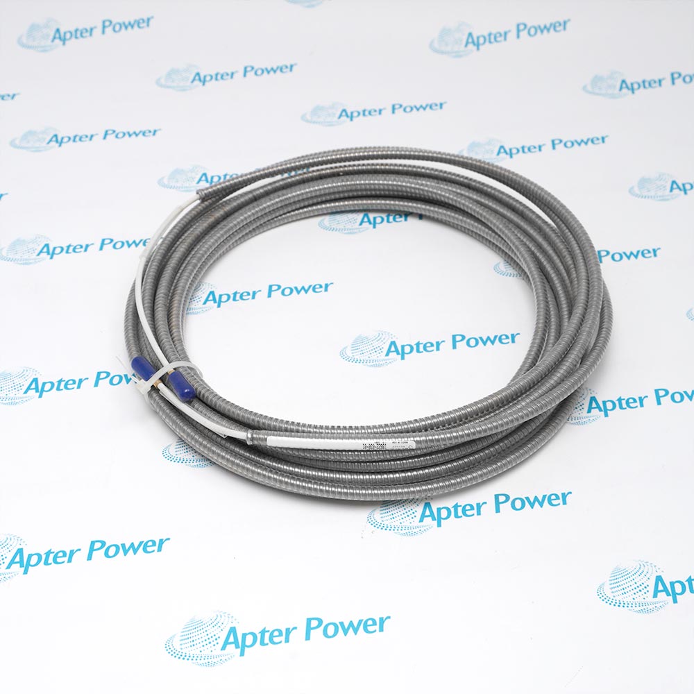
This is a 200152 accelerometer interface standard cable configuration with a connector at the accelerometer end only.

The cable carries the accelerometer signal from the transducer toward the connected monitoring hardware while providing the specified shielded cable construction.

It interfaces with the 20015x accelerometer family through the accelerometer-end connector. The catalogue cable construction uses four 22 AWG conductors, braided shield and drain wire, and a PVC outer jacket.

It supports machine casing vibration channels where the signal cable must be routed from a 20015x accelerometer to the associated monitoring connection.

Ask our team:

Get a quick price for: 200152-XX-XX-XX MOD: 323357-10-03-10
Quantity*
Upload (gif, jpg, jpeg, png, bmp, doc, docx, xls, xlsx, ppt, pdf, csv)
For more information on how your data is processed and stored by Apterpower please read our privacy policy.

Technical specifications for 200152-XX-XX-XX MOD: 323357-10-03-10

Technical specifications for 200152-XX-XX-XX MOD: 323357-10-03-10

  • Manufacturer:
    Bently Nevada
  • Product Category:
    Machinery Monitoring System
  • Spare Part Number:
    200152-XX-XX-XX MOD: 323357-10-03-10
  • Estimated shipping dimensions:
    30x30x8.0cm
  • Weight:
    1.35 kg
  • Tariff Code:
    8537101190
  • Counliy of origin:
    USA
  • Accelerometer-end connector:
    1
  • Conductors:
    4
  • Conductor size:
    22 AWG
  • Minimum bend radius:
    73.7 mm
  • Operating temperature:
    -20 to +100 C

Information

Information

Overview Manuals Common Applications Product Precautions
Bently Nevada 200152-XX-XX-XX MOD: 323357-10-03-10 is a 200152 accelerometer interface standard cable configured for accelerometer-end connector 1 and conductors 4.
  • Accelerometer-end connector: 1
  • Conductors: 4
  • Conductor size: 22 AWG
  • Minimum bend radius: 73.7 mm

The cable transfers the differential accelerometer output toward the connected monitoring hardware through the specified shielded conductor and connector construction.

Configuration control: Match the complete 200152-XX-XX-XX MOD: 323357-10-03-10 code, accelerometer-end connector 1, conductors 4 and mating hardware before mounting or wiring.

Apter Power 200152-XX-XX-XX MOD: 323357-10-03-10 Manuals and Guides

The first five-page document organizes the product identity, technical data, function, application context, compatible components and engineering questions for 200152-XX-XX-XX MOD: 323357-10-03-10. The second five-page guide covers system fit, field planning, installation sequence, commissioning records and diagnostic checks for this complete configuration.

1 cable configuration
200152-XX-XX-XX MOD: 323357-10-03-10 carries the accelerometer signal through the documented connector arrangement.
22 AWG conductor route
The shielded interconnect links a 20015x accelerometer to its associated monitoring connection.
73.7 mm minimum bend control
The cable can be routed through machinery structures while maintaining its stated bend requirement.
Casing-vibration channel wiring
Used between the machine-mounted sensor and the Trendmaster or related monitoring hardware.
Before installing 200152-XX-XX-XX MOD: 323357-10-03-10, confirm the complete catalog code, physical nameplate and selected monitoring-channel configuration.
1
Accelerometer-end connector: 1 is the exact selection for 200152-XX-XX-XX MOD: 323357-10-03-10
2
Conductors: Match 4 to the mating mechanical or electrical interface
3
Conductor size: Retain 22 AWG when selecting the associated system components
4
Minimum bend radius: Verify 73.7 mm before final routing, mounting or commissioning
5
Operating temperature: Record -20 to +100 C in the channel and installation data for this model

Technical notes

Technical notes

Route the cable without bending tighter than the 73.7 mm minimum radius specified for 200152 cable.

FAQS

  • What engineering function does 200152-XX-XX-XX MOD: 323357-10-03-10 perform in its monitoring loop?
    200152-XX-XX-XX MOD: 323357-10-03-10 transports the accelerometer output through shielded conductors to the monitoring interface. Connector count, armor selection and bend control define how the cable is installed.
  • Which accelerometer-end connector applies to 200152-XX-XX-XX MOD: 323357-10-03-10?
    The configured accelerometer-end connector for 200152-XX-XX-XX MOD: 323357-10-03-10 is 1.
  • What conductors must be checked when specifying 200152-XX-XX-XX MOD: 323357-10-03-10?
    Use 4 for the conductors when reviewing this complete model.
  • How does the conductor size selection affect 200152-XX-XX-XX MOD: 323357-10-03-10?
    This configuration identifies conductor size as 22 AWG; include that value in the installation record.
  • Which minimum bend radius is associated with 200152-XX-XX-XX MOD: 323357-10-03-10?
    The technical value is 73.7 mm for the minimum bend radius of this model.
  • What companion hardware should be confirmed for 200152-XX-XX-XX MOD: 323357-10-03-10?
    Confirm compatible 20015x accelerometer, monitoring input or interface module, connector mating hardware named by the cable option.
  • What is the first commissioning check for 200152-XX-XX-XX MOD: 323357-10-03-10?
    Route the cable without bending tighter than the 73.7 mm minimum radius specified for 200152 cable.
  • Where is 200152-XX-XX-XX MOD: 323357-10-03-10 applied and what signal behavior should the engineer verify?
    It supports machine casing vibration channels where the signal cable must be routed from a 20015x accelerometer to the associated monitoring connection. Verify a stable response at the configured monitoring input before releasing the channel.
Trusted by 5,000+ plants worldwide | Backed by our vast inventory of top-tier control parts, modules and cards, fast shipments are dispatched to cover your urgent needs. ABOUT US >>
Disclaimer: We are not an authorized distributor or distributor of the product manufacturer of this website, The product may have older date codes or be an older series than that available direct from the factory or authorized dealers. Because our company is not an authorized distributor of this product, the Original Manufacturer`s warranty does not apply.While many DCS PLC products will have firmware already installed, Our company makes no representation as to whether a DSC PLC product will or will not have firmware and, if it does have firmware, whether the firmware is the revision level that you need for your application. Our company also makes no representations as to your ability or right to download or otherwise obtain firmware for the product from our company, its distributors, or any other source. Our company also makes no representations as to your right to install any such firmware on the product. Our company will not obtain or supply firmware on your behalf. It is your obligation to comply with the terms of any End-User License Agreement or similar document related to obtaining or installing firmware.

We’re Here When You Need Us

From product insights to customer service needs, our experienced service team will focus on getting you what you need quickly

Enquire

Complete our online form.

Call Us

Speak to one of our team.

Live Chat

Send us a message.