-
Match the complete marking
Send the complete 16710-10 cable marking, plug photographs and the identities of both connected devices.
-
Check the offered item before ordering
Request photographs of the plug, terminal lugs and armor. Have your maintenance team compare the offered 16710-10 with the installed cable and applicable Bently Nevada sensor wiring instructions.
Technical specifications for 16710-10
-
Manufacturer:Bently Nevada
-
Product Category:Machinery Monitoring Systems
-
Spare Part Number:16710-10
-
Weight:0.28 kg
-
Tariff Code:8537101190
-
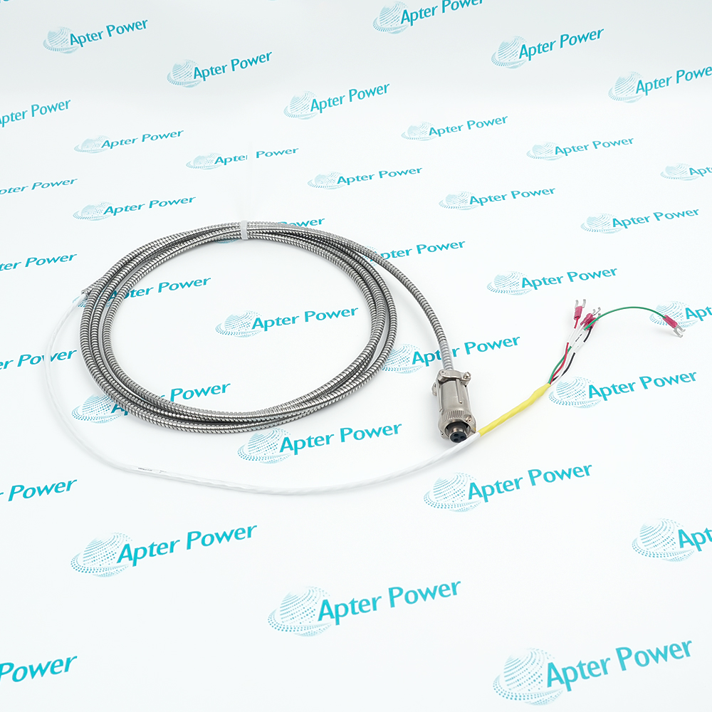
Cable length:10 ft (approximately 3.1 m)
-
Conductors:3
-
Wire size:22 AWG
-
Signal cable shielding:Shielded construction
-
Mechanical protection:Armor
-
Sensor-end termination:3-socket plug
-
Receiving-end termination:Terminal lugs
Information
- Bently Nevada 16710-10 provides a defined cable assembly between a sensor connector and a terminal connection. Its armor supports mechanical protection along the route, while the separate conductor shield serves the signal-wiring arrangement.
Mechanical protection: The armored construction supports a protected route without replacing proper cable support.
Signal integrity: Shielded conductors support the grounding arrangement specified for the connected measurement channel.
The three-socket plug and terminal-lug end perform different connection roles. Socket count alone does not establish power, signal or return assignments. Identify the selected transducer and receiving channel, then use their approved wiring information to map each conductor before reconnecting the assembly.
The shield and armor are separate construction features. Neither should be used as a guessed circuit conductor, and armor does not by itself establish an environmental sealing rating. Final acceptance combines cable inspection and isolated electrical checks with a functional test of the complete measurement path.
16710-10 Official Cable Construction Excerpt
Original English Bently Nevada 16710 cable-construction and accessory entry. PDF · 1 page.16710-10 Installation & Verification Guide
Apter Power cable acceptance workbook with conductor mapping, mechanical inspection, continuity checks and functional handover. PDF · 5 pages.
Application scope: Use the -10 assembly where its complete routed length is sufficient. Transducer, receiving module, mating hardware and mounting accessories are separate items unless the quotation expressly includes them.
Seismic transmitter interconnection
Connect a compatible 177230 transmitter to its approved field termination, preserving the transmitter-specific circuit assignment.Accelerometer signal routing
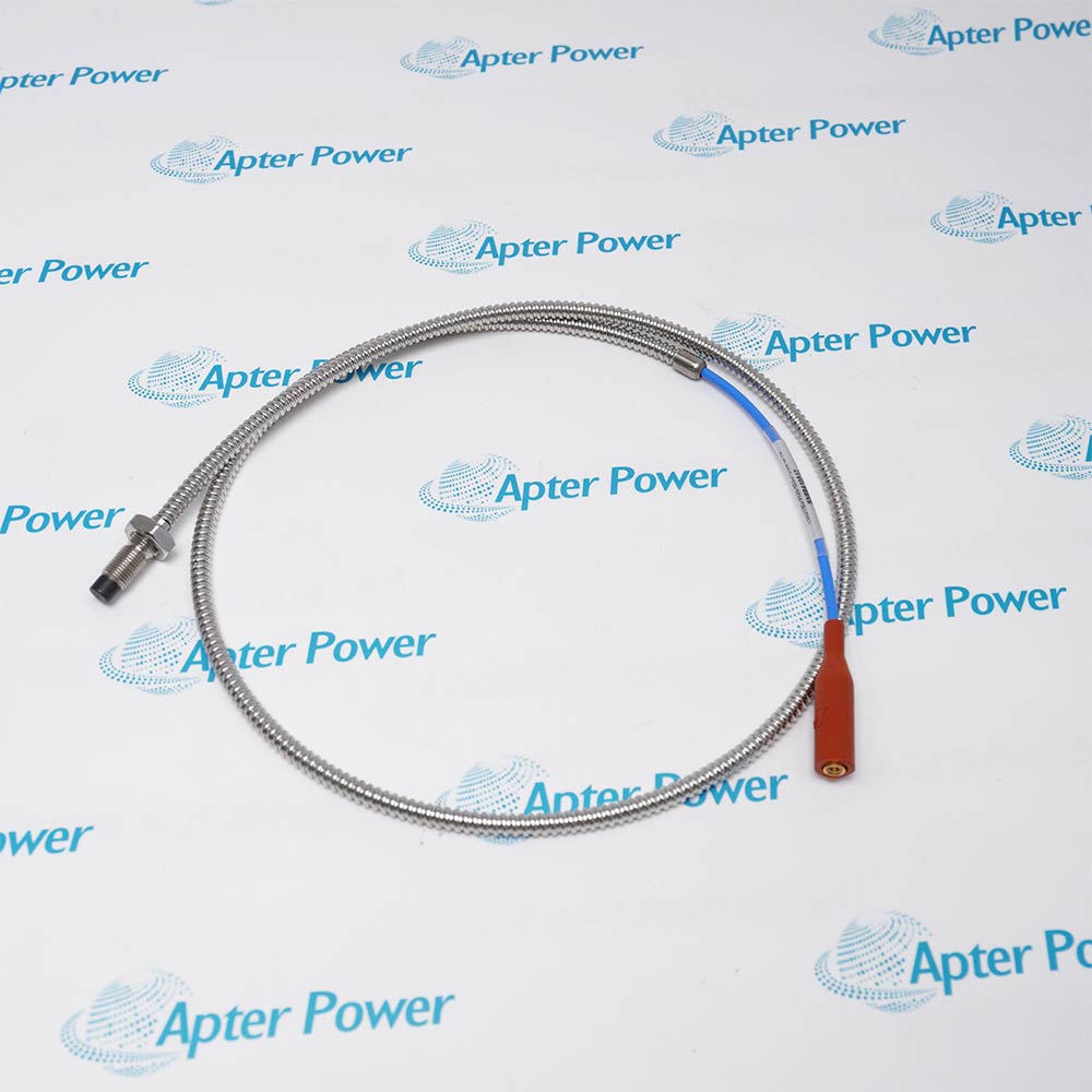
Use the 16710 cable family with a compatible 330400 or 330425 accelerometer and the intended receiving channel.Mechanically exposed cable routes
Apply the armored assembly where route protection is required, together with suitable support and strain relief.Plug-to-terminal interfaces
Bridge a compatible three-socket sensor connection to individually identified terminal lugs without changing the receiving circuit design.
Confirm 16710-10, both connected devices and the original conductor assignment before disconnecting the cable.
Disconnect from sensitive electronics before continuity or other cable testing. Use only test methods permitted by the connected equipment instructions.
Check socket condition, connector engagement and the required sealing arrangement without inferring a cable-wide ingress rating.
Prevent cable tension, crushing and chafing at the connector and terminal ends; armor does not replace strain relief.
Maintain the approved shield termination and circuit return separately. Do not add an unplanned second earth bond.
Check the receiving indication and expected diagnostic response after reconnection before returning the measurement channel to service.
Alternative Names
Technical notes
Length interpretation: The -10 suffix selects ten feet. Assess usable reach along the installed cable route rather than by the straight-line spacing between devices.
Pin assignment boundary: Three sockets and three conductors do not determine polarity. Use the exact transducer and receiving-channel connection instructions.
Electrical test boundary: A continuity result verifies a conductive path; it does not demonstrate noise performance, connector sealing or correct sensor operation.
Shield and return: Keep the circuit-return conductor, shield termination and mechanical armor roles distinct during fault finding.

FAQ View All FAQ
-
Why might 16710-10 fail to reach devices that are less than three metres apart?Straight-line spacing excludes bends, entry routing and service access. Trace the actual supported path and connection approach before selecting the assembly; do not gain reach by placing tension on the plug or lugs.
-
Can the three sockets on 16710-10 be used to infer sensor polarity?No. Socket count describes the connection format, not the circuit assignment. Match each socket and conductor to the exact transducer and receiving-channel wiring before applying power.
-
What does an intermittent reading during a gentle 16710-10 cable movement suggest?An intermittent conductor or termination is one possibility, but the symptom does not identify the faulty component by itself. With the channel safely isolated, inspect the plug and lugs and check continuity while avoiding excessive bending; then verify the complete channel.
-
Why can 16710-10 pass continuity testing while the operating signal remains noisy?Continuity does not verify shield bonding, routing near interference sources or the receiver configuration. Review the approved shield termination and cable route, then compare the channel response under controlled operating conditions.
-
Should the armor of 16710-10 be connected as the circuit return?Do not substitute armor for an assigned conductor. Preserve the sensor circuit return and approved shield/earth arrangement, and check the actual terminal map before energizing the channel.
-
Can 16710-10 be joined to another cable to extend an accelerometer route?A splice introduces a new termination and shielding boundary. Use an approved complete cable arrangement and check the connected transducer’s cable requirements rather than assuming that matching conductor count makes a joint acceptable.
-
Does installing 16710-10 make the complete sensor connection waterproof?No sealing conclusion follows from armor alone. Verify the connector mating and sealing requirements of the exact sensor, and inspect the assembled connection before use in the intended environment.
-
What should be checked if the receiver loses its signal immediately after a 16710-10 replacement?First compare conductor assignments and terminal engagement with the retained wiring record. Then check the intended sensor supply and receiver setup using the approved procedure. A correct-looking plug does not establish a correct end-to-end circuit.
Supporting new and legacy automation
-
Please try to be as accurate as possible with your search.
-
We can quote you on 1000s of specialist parts, even if they are not listed on our website.
-
We can't find any results for “”.
Related cases and sourcing guidance
View all case studiesYou May Also Like
Product Browsing History
-
Whatsapp: +86 18030235313
Send us a message. -
sales13@apterpower.com
Complete our online form. -
+86 18030235313
Speak to our team in your native language.